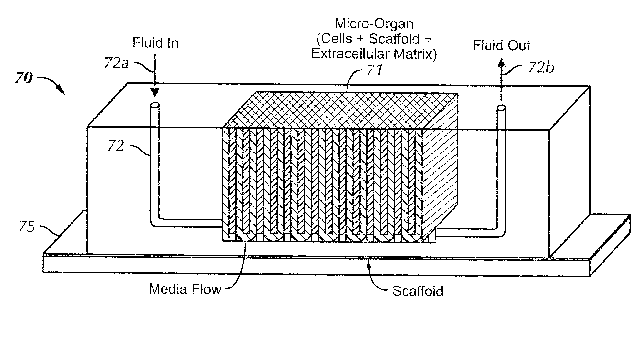
Micro-organ device

a microorganism and device technology, applied in the field of microorganism devices, can solve the problems of difficult extrapolation of in vitro data (e.g., cell culture data) to the in vivo relevant conditions, and the inability to test pharmaceuticals and biological compounds in humans or animals is not always possible,

Active Publication Date: 2013-01-01
NASA
View PDF17 Cites 37 Cited by
  • Summary
  • Abstract
  • Description
  • Claims
  • Application Information

AI Technical Summary

Problems solved by technology

Testing of pharmaceuticals and biological compounds in humans or in animals is not always possible, at least not in the early stage.
Moreover, while in vivo animal studies can provide data more relevant to human responses, animal tests are expensive, labor-intensive, and time consuming.
However, extrapolating in vitro data (e.g., cell culture data) to the in vivo relevant conditions is often difficult.
Although pharmacokinetic principles can be used to derive some conclusions, this approach has limitations due to various reasons.
For example, cell cultures under traditional assay conditions may not function in the same ways as cells would in natural settings because the communication and interactions between different tissues and organs are absent.
These systems may have unrealistically high liquid-to-cell ratios.
Even if the cells are grown on microcarrier beads, which more closely resemble physiological conditions, they still may not mimic physiological conditions accurately enough to provide reliable data.
Additionally, while controlling the spatial orientation of cells having a cell-cell interaction in a co-culture would improve traditional cell culture methods, the cell-cell interactions between different cell types do not always allow proper interactions between different cell types.
Consequently, methods of predicting human response from in vitro cell culture assays are complicated, and systems or devices of the related art designed to replicate in vivo organs or systems of humans or animals have not performed quite as predicted.
These approaches do not always provide reproducible organs.

Method used


Image

  • Micro-organ device
  • Micro-organ device
  • Micro-organ device

Examples


Embodiment Construction

[0026]Exemplary embodiments of the invention will now be described with reference to the accompanying figures. Like elements or components in the figures are denoted with the same reference characters for consistency.

[0027]Before beginning a detailed description of some exemplary embodiments of the invention, the meaning of certain terms as used herein will be given.

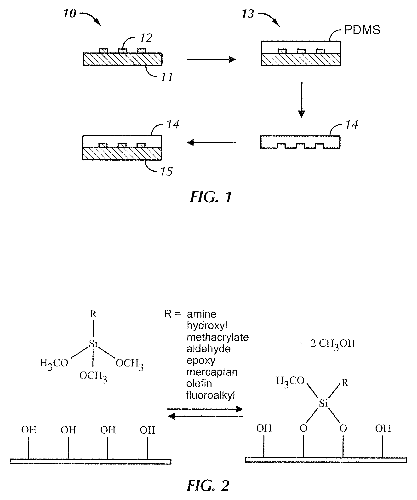
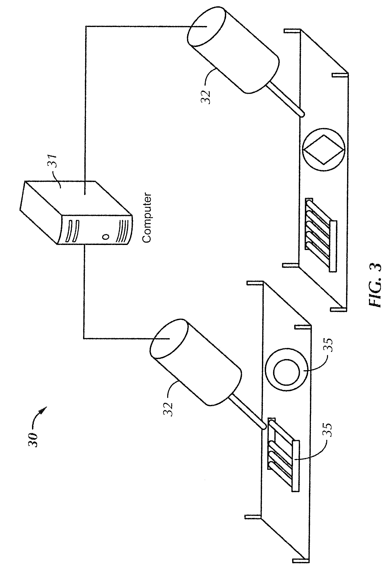
[0028]“Bioprint” or “bioprinting”, as used in this description, refers to a process of depositing biological materials, such as, for example, forming micro-organs using a computer-aided tissue engineering (CATE) system to print a micro-organ according to a particular design or pattern. These processes will be described in more detail below.

[0029]“Microscale” as used herein refers to dimensions no greater than 10 cm, preferably no greater than 1 cm.

[0030]“Microchip” as used herein refers to a microscale support having one or more microfluidic channels and one or more micro-chambers for housing micro-organs. A microchip ty...


PUM

PropertyMeasurementUnit
widthaaaaaaaaaa
temperatureaaaaaaaaaa
widthaaaaaaaaaa

Abstract

A method for fabricating a micro-organ device comprises providing a microscale support having one or more microfluidic channels and one or more micro-chambers for housing a micro-organ and printing a micro-organ on the microscale support using a cell suspension in a syringe controlled by a computer-aided tissue engineering system, wherein the cell suspension comprises cells suspended in a solution containing a material that functions as a three-dimensional scaffold. The printing is performed with the computer-aided tissue engineering system according to a particular pattern. The micro-organ device comprises at least one micro-chamber each housing a micro-organ; and at least one microfluidic channel connected to the micro-chamber, wherein the micro-organ comprises cells arranged in a configuration that includes microscale spacing between portions of the cells to facilitate diffusion exchange between the cells and a medium supplied from the at least one microfluidic channel.

Description

CROSS REFERENCE TO RELATED APPLICATIONS[0001]The application claims the benefit of U.S. Provisional Application Ser. No. 60 / 908,918, filed on Mar. 29, 2007. This provisional application is incorporated herein by reference in its entirety.ORIGIN OF INVENTION[0002]The invention described herein was made in the performance of work under a NASA contract and is subject to Public Law 96-517 (35 U.S.C. §200 et seq.). The contractor has not elected to retain title to the invention. The invention described herein was also made by employee(s) of the United States Government and may be manufactured and used by or for the Government of the United States of America for governmental purposes without the payment of any royalties thereon or therefor.BACKGROUND OF INVENTION[0003]1. Field of Invention[0004]The invention relates generally to devices for testing of biologics. More particularly, this invention relates to micro-organ devices and methods for fabricating and using such devices.[0005]2. Dis...

Claims


Application Information

Patent Timeline
Patent Type & Authority Patents(United States)
IPC IPC(8): C12N11/00C12N11/16C12N9/00C12P21/04C12N9/99
CPCC12M21/08C12M23/16C12M25/14C12N5/0671C12Q1/025B01L3/5027C12N2533/74B33Y80/00C12Q1/02
Inventor GONDA, STEVE R.CHANG, ROBERT C.STARLY, BINILCULBERTSON, CHRISTOPHERHOLTORF, HEIDI L.SUN, WEILESLIE, JULIA
Owner NASA
Why Eureka
Try Eureka