Input apparatus

a technology of input apparatus and input tube, which is applied in the field of input apparatus, can solve the problems and achieve the effect of increasing the cost of the multiple operation type input apparatus

Inactive Publication Date: 2013-01-01
HOSIDEN CORP
View PDF11 Cites 99 Cited by
  • Summary
  • Abstract
  • Description
  • Claims
  • Application Information

AI Technical Summary

Benefits of technology

[0007]The above conventional apparatus requires four magnets and four Hall-effect devices in the first detector. With such configuration, the apparatus has a larger number of components, resulting in increased costs of the multiple-operation type input apparatus.
[0008]The present invention is devised in view of the above-described circumstances. The invention provides an input apparatus that can be manufactured with a reduced number of magnetic sensors and in a reduced cost.

Problems solved by technology

With such configuration, the apparatus has a larger number of components, resulting in increased costs of the multiple-operation type input apparatus.

Method used


Image

  • Input apparatus
  • Input apparatus
  • Input apparatus

Examples


Embodiment Construction

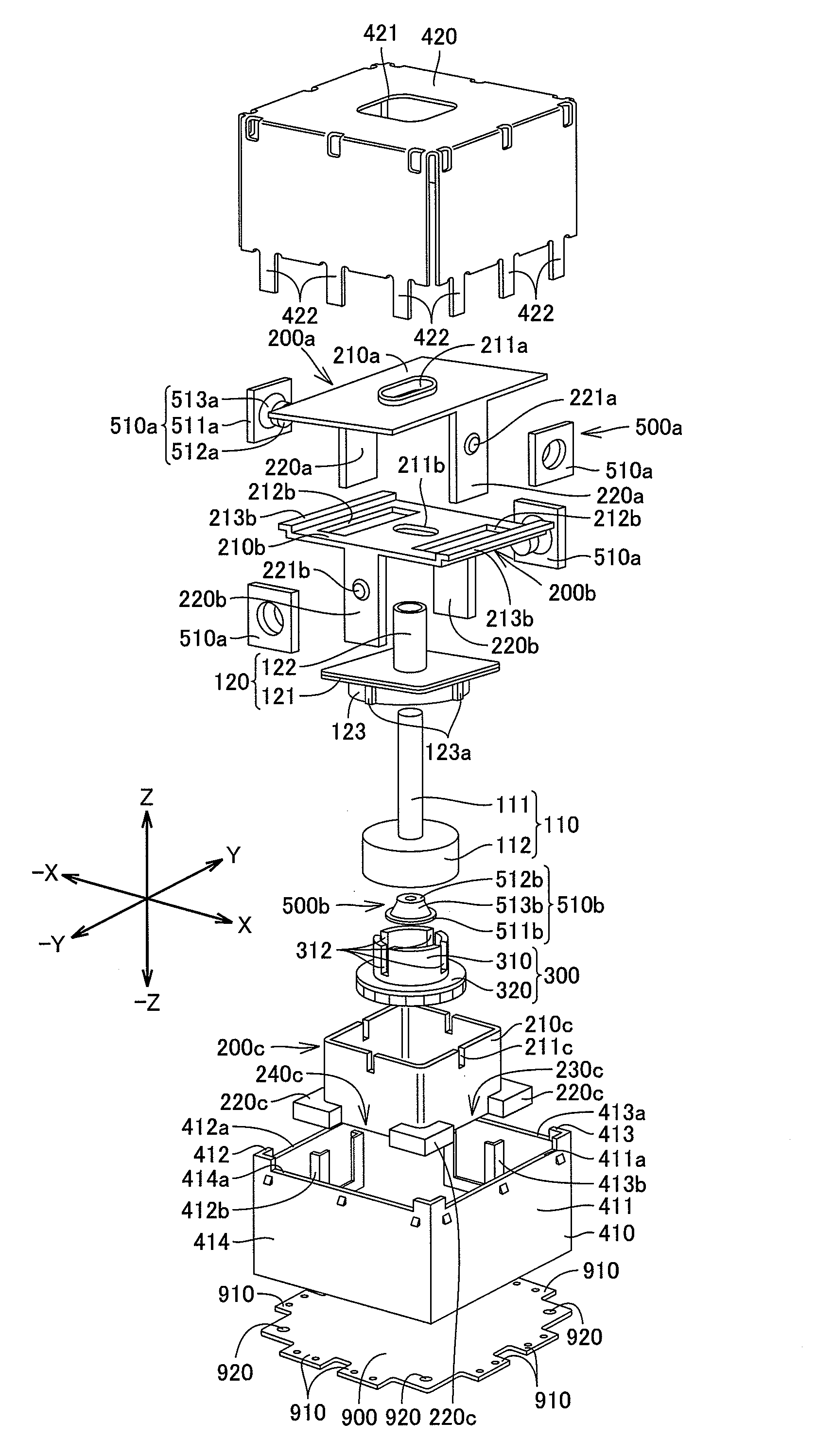
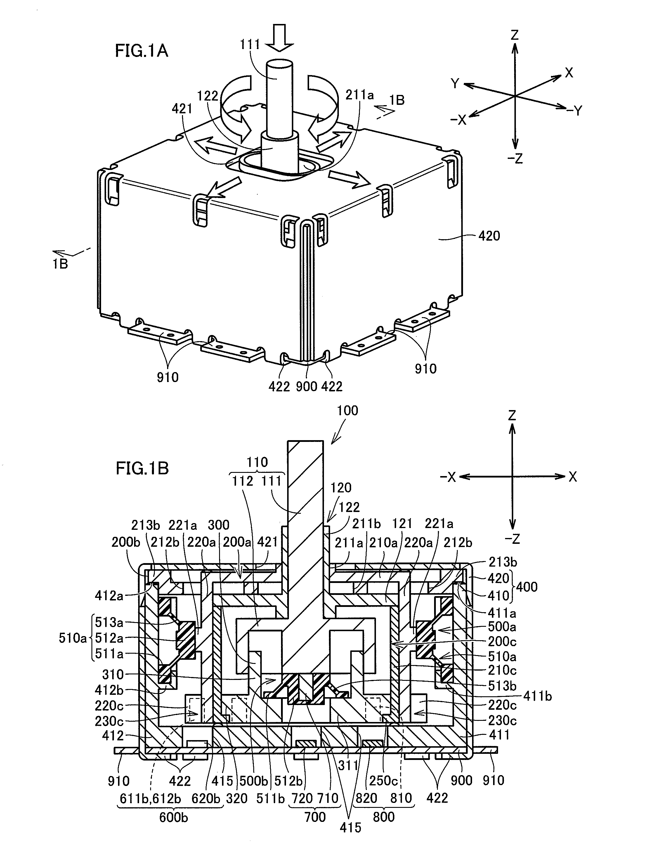
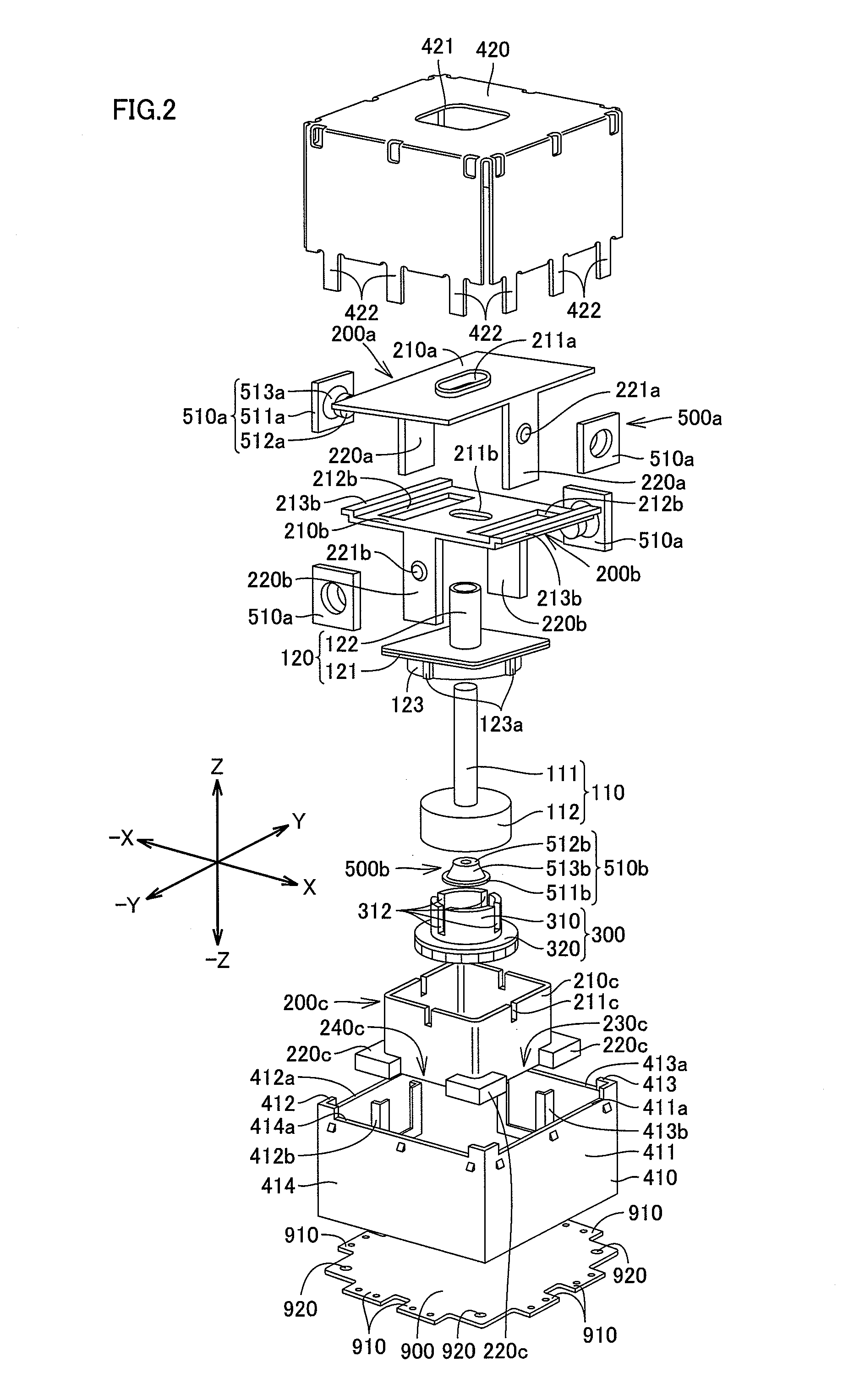
[0041]An input apparatus according to an embodiment of the present invention will be described below referring to FIGS. 1 to 12. The input apparatus as shown in FIGS. 1A and 1B is a multiple operation-type input apparatus having a slide operation input function enabling an operating member 100 to perform slide operation input in eight directions of X, −X, Y, −Y, XY, −X-Y, X-Y, −XY from a neutral position, a press operation input function enabling the operating member 100 to perform press operation input in a −Z direction from the neutral position, and a rotation operation input function enabling the operating member 100 to perform rotational operation input in a circumferential direction. The input apparatus has the operating member 100, first, second and third sliders 200a, 200b, 200c, a rotating member 300, a case 400, first and second neutral position returning mechanisms 500a, 500b, first and second slide detectors 600a, 600b, a press detector 700, a rotation detector 800, and a...


PUM


Abstract

The invention provides an input apparatus An input apparatus according to the present invention includes: an operating member, operable to move in at least X and −X directions from a neutral position; first and second magnets, being arranged with spacing along an X and −X direction and having opposite magnetic polarities to each other, wherein when the operating member moves in either one of the two directions, the first and second magnets moves in the same direction as the operating member; and a first magnetic sensor, provided at a position displaced from a middle point between the two magnets when the operating member is located in the neutral position, the position being equidistant from the two magnets. When the operating member moves in one of the two directions, the first magnetic sensor outputs a signal in accordance with the magnetic polarity of one of the first and second magnets.

Description

[0001]The present application claims priority under 35 U.S.C. §119 of Japanese Patent Application No. 2010-007281 filed on Jan. 15, 2010, the disclosure of which is expressly incorporated by reference herein in its entity.BACKGROUND OF THE INVENTION[0002]1. Technical Field[0003]The present invention relates to input apparatuses that can be operated to move at least in X, and −X directions.[0004]2. Background Art[0005]A conventional input apparatus of this types, as disclosed in Japanese Unexamined Patent Publication No. 2004-288459, has a first detector to detect movement in X, −X, Y and −Y directions of an operating member operated, and a second detector to detect press operation of the operating member. The first detector has four magnets, provided at positions corresponding to the X, −X, Y and −Y directions in a base of the operating member, and four Hall-effect devices arranged on a printed circuit board so as to correspond to the magnets.CITATION LIST[0006]Patent Literature 1: ...

Claims


Application Information

Patent Timeline
Patent Type & Authority Patents(United States)
IPC IPC(8): H01H9/00G06F3/02
CPCG06F3/0338H01H25/04
Inventor NIIYAMA, TAKASHI
Owner HOSIDEN CORP
Why Eureka
Try Eureka