Method for controlling a power driver

a technology of power driver and motor assembly, which is applied in the field of driving tools, can solve the problems of not providing the user with the desired degree of flexibility and freedom

Active Publication Date: 2013-01-08
BLACK & DECKER INC
View PDF108 Cites 814 Cited by
  • Summary
  • Abstract
  • Description
  • Claims
  • Application Information

AI Technical Summary

Benefits of technology

[0007]Further areas of applicability of the present invention will become apparent from the detailed description provided hereinafter. It should be understood that the detailed description and specific examples, while indicating the preferred embodiment of the invention, are intended for purposes of illustration only and are not intended to limit the scope of the invention.

Problems solved by technology

Often times, however, the power nailers that are available may not provide the user with a desired degree of flexibility and freedom due to the presence of hoses and such that couple the power nailer to a source of pneumatic power.

Method used


Image

  • Method for controlling a power driver
  • Method for controlling a power driver
  • Method for controlling a power driver

Examples


Embodiment Construction

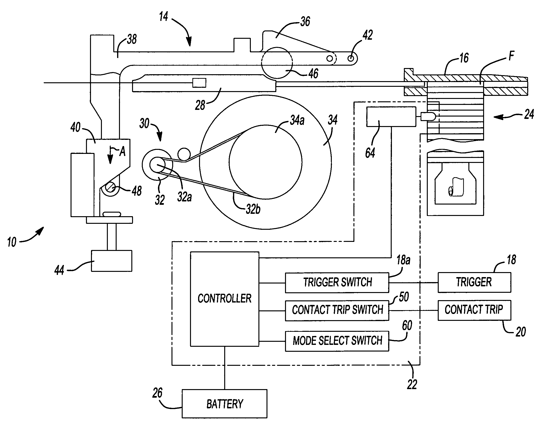
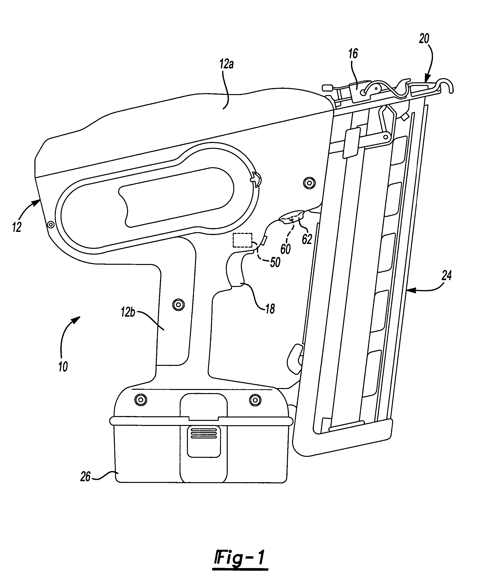
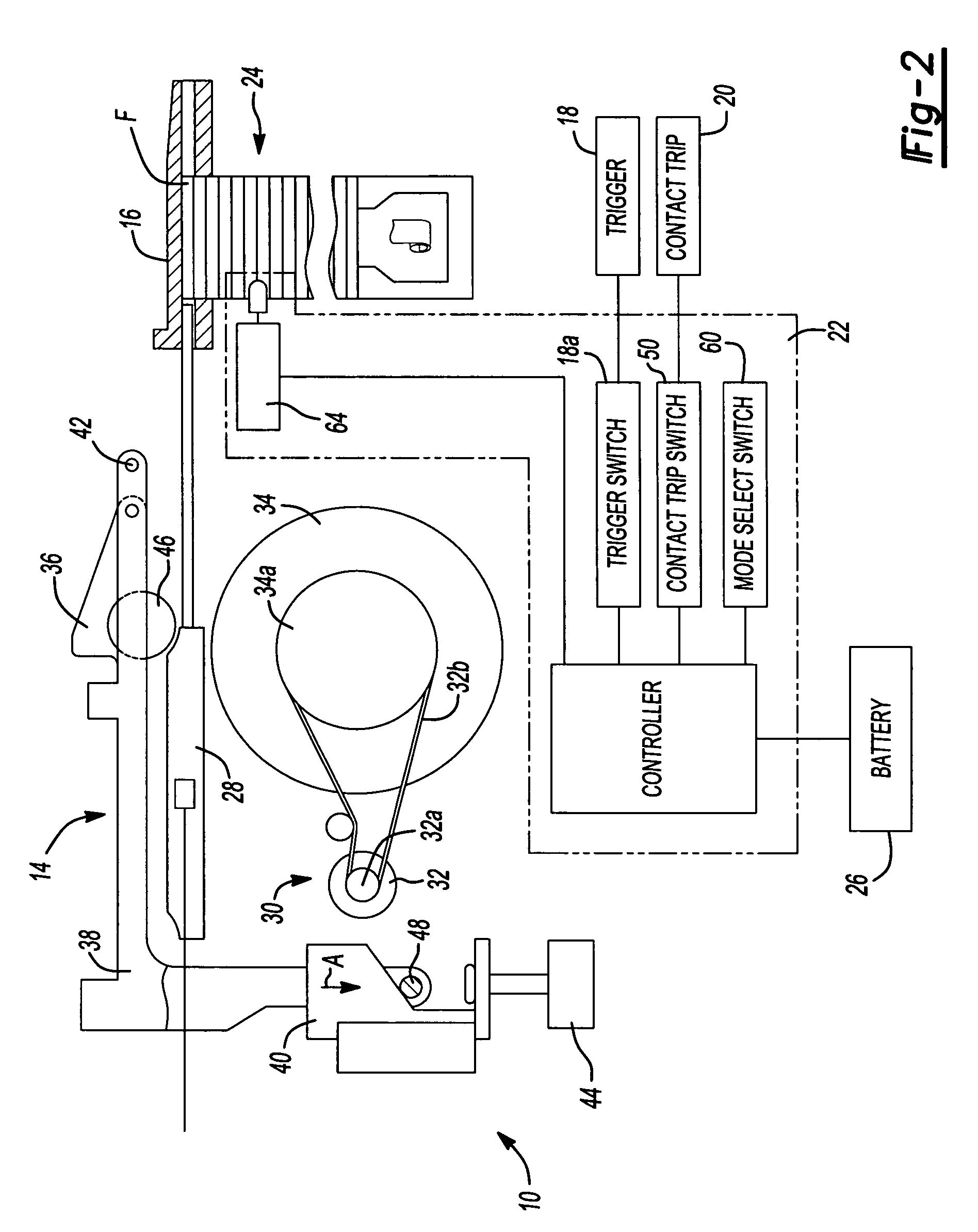
[0017]With initial reference to FIG. 1, an electric fastener delivery device, which may be referred to herein as a nailer, is generally indicated by reference numeral 10. While the electric fastener delivery device is generally described in terms of a fastening tool 10 that drives nails into a workpiece, the electric fastener delivery device may be configured to deliver different fasteners, such as a staple or screw, or combinations of one or more of the different fasteners. Further, while the fastening tool 10 is generally described as an electric nailer, many of the features of the fastening tool 10 described below may be implemented in a pneumatic nailer or other devices, including rotary hammers, hole forming tools, such as punches, and riveting tools, such as those that are employed to install deformation rivets.

[0018]With continuing reference to FIG. 1 and additional reference to FIGS. 2 and 3, the fastening tool 10 may include a housing 12, a motor assembly 14, a nosepiece 16...


PUM

PropertyMeasurementUnit
voltageaaaaaaaaaa
voltageaaaaaaaaaa
voltageaaaaaaaaaa

Abstract

A driving tool having a driver, a power source, a sensor and a controller. The power source selectively provides an input to the driver to cause the driver to translate along an axis. The sensor senses a condition in the power source that is indicative of a level of kinetic energy of an element in the power source and generates a sensor signal in response thereto. The controller is coupled to the power source and the sensor and is responsive to the sensor signal for deactivating the power source to inhibit the power source from providing the input to the driver when the level of kinetic energy of the element in the power source is below a predetermined threshold. A method for operating a driving tool is also provided.

Description

CROSS-REFERENCE TO RELATED APPLICATIONS[0001]This application claims priority to U.S. Provisional Patent Application Ser. No. 60 / 559,349 filed Apr. 2, 2004 entitled “Fastening Tool”.FIELD OF THE INVENTION[0002]The present invention generally relates to driving tools, such as fastening tools, and more particularly to a driving tool with a motor assembly that can be selectively controlled depending upon an amount of kinetic energy that is stored in the motor assembly.BACKGROUND OF THE INVENTION[0003]Power nailers are relatively common place in the construction trades. Often times, however, the power nailers that are available may not provide the user with a desired degree of flexibility and freedom due to the presence of hoses and such that couple the power nailer to a source of pneumatic power. Accordingly, there remains a need in the art for an improved power nailer.SUMMARY OF THE INVENTION[0004]In one form, the teachings of the present invention provide a driving tool having a driv...

Claims


Application Information

Patent Timeline
Patent Type & Authority Patents(United States)
IPC IPC(8): B25B21/02B25C1/00B25C1/06B25D1/00H01H15/02H02K7/02
CPCB25C1/06
Inventor FORSTER, MICHAELSCHELL, CRAIG A.GROSS, PAULBRADENBAUGH, IV, CHARLES L.CRUISE, NATHANEKSTROM, ERIK
Owner BLACK & DECKER INC
Why Eureka
Try Eureka