Vehicular lamp unit and vehicular lamp

a technology for vehicular lamps and lamps, which is applied in the manufacture of electric discharge tubes/lamps, electrode systems, lighting and heating apparatuses, etc., can solve the problems of difficult to recognize objects on the opposite lane, poor visibility, and inability to radiate light above the cut-off line of light distribution patterns, etc., to improve forward visibility.

Inactive Publication Date: 2013-01-08
KOITO MFG CO LTD
View PDF11 Cites 16 Cited by
  • Summary
  • Abstract
  • Description
  • Claims
  • Application Information

AI Technical Summary

Benefits of technology

[0009]However, even when a part of the reflected light from the main reflector is reflected upward by the second reflective surface of the sub-reflector as in the above-described lamp unit, the light cannot be radiated at all above the cut-off line of the light distribution pattern. If the light is not radiated at all above the cut-off line, a forward visibility is not good, and it is hard to recognize an object on an opposite lane. Specifically, radiated light with such a level that the light does not give a glare to a vehicle on the opposite lane is necessary for improving the forward visibility also above a cut-off line in a low-beam light distribution pattern.
[0010]Accordingly, one or more embodiments of the present invention provide a vehicular lamp unit and a vehicular lamp capable of improving a forward visibility by radiating light also above a cut-off line of a light distribution pattern.
[0014]With the use of the vehicular lamp unit having such a structure, because the reflector can be used for both the vehicular lamp unit for right-side light distribution and the vehicular lamp unit for left-side light distribution, the number of parts can be reduced.
[0016]With the use of the vehicular lamp structured as above, when light distributions from a plurality of lamp units are combined to form an entire light distribution pattern, by forming the first reflective surface and the second reflective surface on the reflector and the shade, respectively, in a diffusing-type lamp unit having a light collecting power lower than that of another vehicular lamp unit, it is possible to easily radiate above the cut-off line of the light distribution pattern in a diffused manner along a vehicle width direction.
[0017]With the use of the vehicular lamp unit according to one or more embodiments of the present invention, the light incident on the projection lens from the second reflective surface after being reflected by the first reflective surface is emitted as the upward directed radiated light, which enables to radiate above the cut-off line of the light distribution pattern. Accordingly, it is possible to improve the forward visibility.

Problems solved by technology

However, even when a part of the reflected light from the main reflector is reflected upward by the second reflective surface of the sub-reflector as in the above-described lamp unit, the light cannot be radiated at all above the cut-off line of the light distribution pattern.
If the light is not radiated at all above the cut-off line, a forward visibility is not good, and it is hard to recognize an object on an opposite lane.

Method used


Image

  • Vehicular lamp unit and vehicular lamp
  • Vehicular lamp unit and vehicular lamp
  • Vehicular lamp unit and vehicular lamp

Examples


Embodiment Construction

[0027]Hereafter, embodiments of a vehicular lamp unit and a vehicular lamp according to the present invention will be described in detail with reference to accompanying drawings.

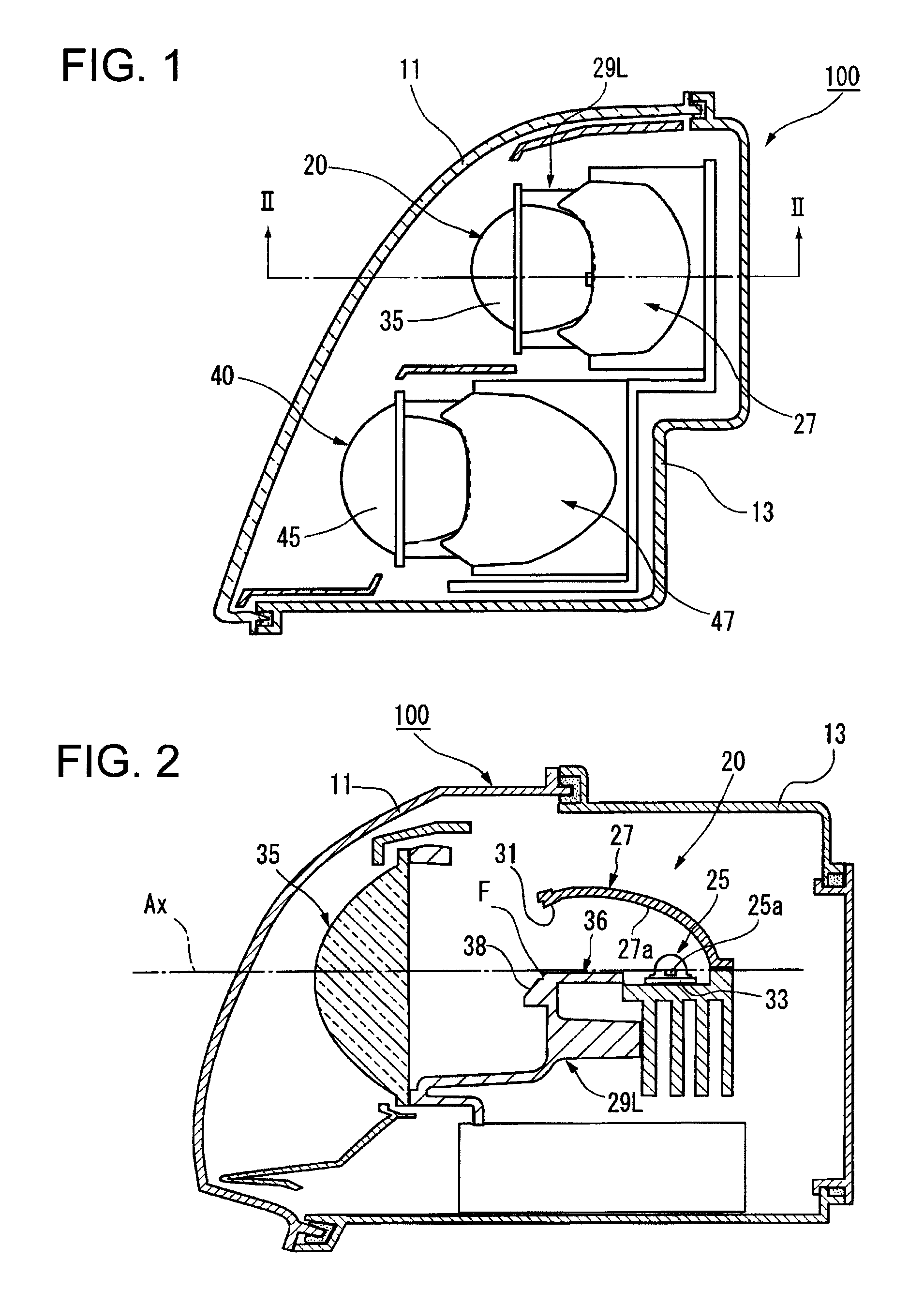
[0028]FIG. 1 is a horizontal cross sectional view of a vehicular lamp according to one or more embodiments of the present invention.

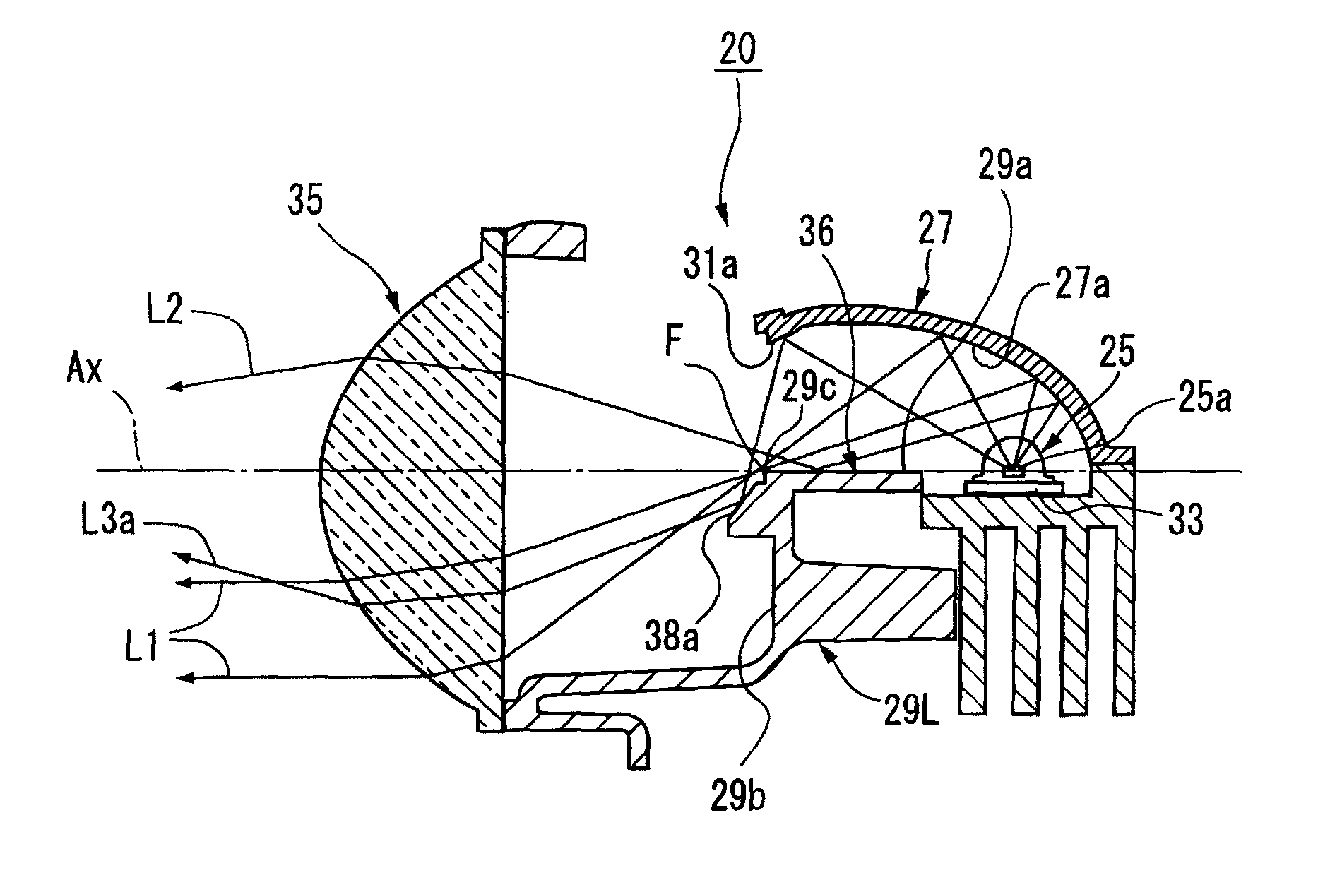
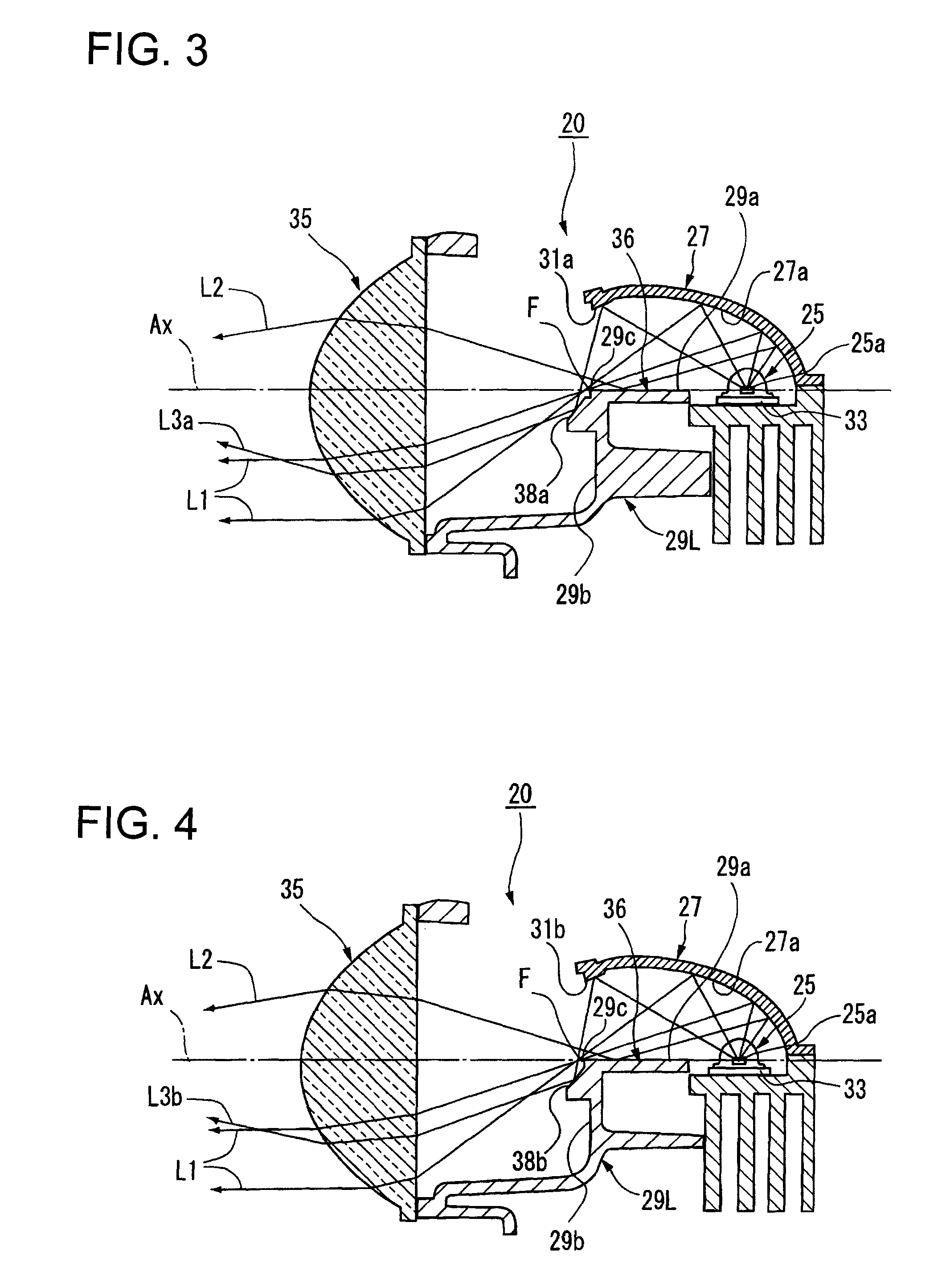
[0029]A vehicular lamp 100 is a low-beam headlamp, and is structured such that, in a lamp chamber formed of a plain translucent cover 11 and a lamp body 13, a plurality of lamp units (two are shown) are housed side-by-side. The plurality of lamp units are formed of a lamp unit (vehicular lamp unit) 20 having a low light collecting power and another lamp unit (another vehicular lamp unit) 40 having a light collecting power higher than that of the lamp unit 20.

[0030]These lamp units 20, 40 are supported in the lamp body 13 via a frame (not shown), and the frame is supported in the lamp body 13 via an aiming mechanism (not shown).

[0031]The aiming mechanism is a mechanism for finely...


PUM


Abstract

A vehicular lamp unit includes a projection lens disposed on an optical axis extending in a vehicular longitudinal direction; a light source disposed rearward of a rear side focal point of the projection lens; a reflector reflecting direct light from the light source forward towards the optical axis; a shade disposed between the projection lens and the light source such that the shade blocks a part of reflected light from the reflector and a part of the direct light from the light source to form a cut-off line of a light distribution pattern; a first reflective surface formed on a tip portion of the reflector such that the first reflective surface reflects a part of the direct light from the light source downward to the front of the shade; and a second reflective surface formed on the front of the shade and below the rear side focal point of the projection lens such that the second reflective surface reflects reflected light from the first reflective surface towards the projection lens. The first reflective surface is formed in a shape of an ellipsoidal reflective surface having a vertical cross-section that is generally ellipsoidal in shape, and the second reflective surface is formed in a generally flat shape having a linear vertical cross-section.

Description

BACKGROUND OF INVENTION[0001]1. Field of the Invention[0002]The present invention relates to a vehicular lamp unit and a vehicular lamp of so-called projector-type, and particularly relates to a vehicular lamp unit and a vehicular lamp provided with a shade that forms a cut-off line of a light distribution pattern.[0003]2. Related Art[0004]Conventionally, as one form of a vehicular lamp such as a headlamp, a so-called projector-type vehicular lamp is known. This projector-type vehicular lamp is structured to collect and reflect light from a light source disposed on an optical axis to the front towards the optical axis using a reflector, and to radiate the reflected light to the front of the lamp via a projection lens provided in front of the reflector.[0005]It is common that, when such a projector-type lamp unit is used as a low-beam headlamp, a shade is provided between the projection lens and the light source, and a part of the reflected light from the reflector and a part of dire...

Claims


Application Information

Patent Timeline
Patent Type & Authority Patents(United States)
IPC IPC(8): B60Q1/00H01J9/24F21V7/00
CPCF21S48/1159F21S48/1382F21S48/145F21S48/1388F21S41/148F21S41/255F21S41/321F21S41/338F21S41/365F21S41/43
Inventor NAKADA, YUSUKE
Owner KOITO MFG CO LTD
Why Eureka
Try Eureka