Lens driving device, flexible piece and the method for manufacturing the flexible piece

a technology of lens driving device and flexible piece, which is applied in the direction of manufacturing tools, instruments, television systems, etc., can solve the problems of excessively long oscillation time, relatively slow recovery provided by vcm, and inability to adjust the speed of the lens, so as to reduce the opening speed of the gap, shorten the oscillation time, and effectively absorb the associated wobble

Inactive Publication Date: 2013-01-08
WAH HONG INDAL CORP
View PDF4 Cites 6 Cited by
  • Summary
  • Abstract
  • Description
  • Claims
  • Application Information

AI Technical Summary

Benefits of technology

[0011]The present invention provides a lens displacement device, a flexible piece and a manufacturing process thereof, wherein the lens displacement device incorporates an internally installed flexible piece to achieve the objectives of effectively shortening the oscillation time required for the lens to position and accelerating the responsive speed toward a steady state.
[0018]In summary, the present invention features the installation of an oscillation absorber in the gap existing between the support and the flexible part of the flexible piece or otherwise installs an oscillation absorber in the gap existing in the flexible part. In doing so, the present invention is capable of reducing an opening speed of the gap of the flexible piece and effectively absorbing the wobbles associated with the flexible piece in order to shorten an oscillation time and accelerate the responsive speed toward a steady state.

Problems solved by technology

However, a restoration provided by VCM may take several milliseconds, which is relatively slower compared with other displacement methods, and thus at least one flexible component is additionally installed within the VCM to accelerate the restoration.
However, the aforementioned flexible component may undesirably result in excessively long oscillation time over the course of the positioning of the lens holder as well, undermining performance of an lens device featuring tracking AF.

Method used


Image

  • Lens driving device, flexible piece and the method for manufacturing the flexible piece
  • Lens driving device, flexible piece and the method for manufacturing the flexible piece
  • Lens driving device, flexible piece and the method for manufacturing the flexible piece

Examples


first embodiment

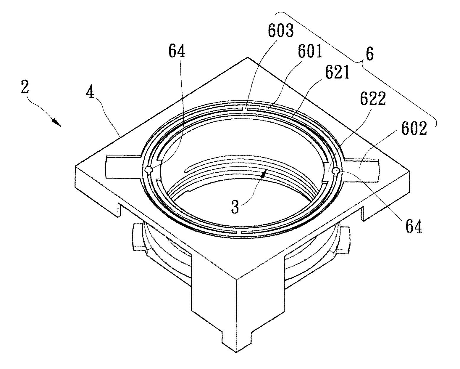
[0034]Refer next to FIG. 4, wherein a perspective view of a lens displacement device according to the present invention is shown. The flexible piece 6 may be installed inside a lens displacement device 2, or called lens driving device. The lens displacement device 2 includes the flexible piece 6, a mobile element 3 and a fixed element 4. The mobile element 3, or called movement barrel, has a lens holder (not shown) for carrying a lens assembly and a magnetic component. The magnetic component is installed on the lens holder. Besides, the fixed element 4, or called fixed barrel, includes a fixed seat and a coil assembly installed inside of the fixed seat. The aforementioned mobile element 3 and fixed element 4 are of well-known technologies whose relevant structures will not be further illustrated for a compact prosecution of the application.

[0035]As depicted in FIG. 4, relative to the fixed element 4, the mobile element 3 in the lens displacement device 2 may be movably installed ins...

second embodiment

[0041]As shown in FIG. 6, in the second embodiment, the support 70 of the flexible piece 7 consists of two first plates, the displacing part 721 of the flexible part 72 consists of two second plates, and the meandering part 722 of the flexible part 72 has four meandering bodies. Each of the meandering bodies may be connected to the first plate and the second plate and may be located between the first plate and the second plate, so as to form the flexible piece 7 in the single-ring closed structure.

[0042]Refer once again to FIG. 6, in which a manufacturing process for the flexible piece according to the second embodiment of the present invention is described. The manufacturing process comprises the following steps: preparing a flexible substrate, forming the flexible piece 7 including the support 70 and the flexible part 72 connected to the support 70, and at least one gap 76 in the meandering part 722 of the flexible part 72, and installing the oscillation absorber 74 in the gap 76....


PUM

PropertyMeasurementUnit
flexibleaaaaaaaaaa
oscillation timeaaaaaaaaaa
distanceaaaaaaaaaa

Abstract

A lens displacement device includes a flexible piece, a fixed element and a mobile element. The flexible piece has a support, a flexible part and an oscillation absorber. The flexible part connects to the support and at least one gap exists between the flexible part and the support. The oscillation absorber is installed in the gap between the flexible part and the support. Moreover, the fixed element couples to the support of the flexible piece, and the mobile element couples to the flexible part of the flexible piece. Furthermore, the flexible part of the flexible piece is deformed in shape for providing a restoration force with the mobile element. A manufacturing process of the flexible piece is also disclosed.

Description

BACKGROUND OF THE INVENTION[0001]1. Field of the Invention[0002]The present invention relates to a lens displacement device; in particular, to a lens displacement device applicable for driving a micro imaging module lens and shortening the oscillation time.[0003]2. Description of Related Art[0004]An optical auto-focusing (AF) is to suitably move lens in an imaging module based on distance of an object from the lens, further allowing an optical image of the object to be accurately focused on an image sensor thereby creating a clear image. At the present, commonly used lens displacement devices for enabling movement of the lens in the imaging module may include a step motor, a piezoelectric motor and a voice coil motor (VCM) and the like.[0005]Typically, mechanism of VCM is essentially implemented by placing a coil in the magnetic circuit comprising a permanent magnet. Therefore, according to Fleming's left-hand rule, the coil generates a driving force, which is from an interaction wi...

Claims


Application Information

Patent Timeline
Patent Type & Authority Patents(United States)
IPC IPC(8): G02B7/02
CPCG02B7/023G02B13/001H04N5/23212G02B26/0875Y10T29/49826
Inventor KUO, LI-TECHEN, CHIEN-LIANGLAI, MEI-LINGCHANG, WEN-HSIUNG
Owner WAH HONG INDAL CORP
Why Eureka
Try Eureka