Time generator for power converter and method for generating time signal

A power converter, time signal technology, applied in the output power conversion device, electrical components, DC power input into DC power output and other directions, to achieve the effect of stabilizing the output voltage and shortening the oscillation time

Active Publication Date: 2016-12-28
UPI SEMICON CORP
View PDF7 Cites 0 Cited by
  • Summary
  • Abstract
  • Description
  • Claims
  • Application Information

AI Technical Summary

Problems solved by technology

[0004] In view of this, the present invention proposes a time generator and a time signal generation method for power converters, so as to solve the problems mentioned in the prior art

Method used


Image

  • Time generator for power converter and method for generating time signal
  • Time generator for power converter and method for generating time signal
  • Time generator for power converter and method for generating time signal

Examples


Embodiment Construction

[0080] Reference will now be made in detail to embodiments of the present invention, examples of which are illustrated in the accompanying drawings. In addition, elements / components with the same or similar numbers used in the drawings and embodiments are used to represent the same or similar parts.

[0081] In the following embodiments, when an element is referred to as being “connected” or “coupled” to another element, it may be directly connected or coupled to the other element, or there may be intervening elements. The term "circuitry" means at least one element or elements, or elements that are actively and / or passively coupled together to provide a suitable function. The term "signal" means at least one current, voltage, load, temperature, data or other signal. The ramp signal can also be a ramp-like signal, a triangular ramp signal or a saw-tooth ramp signal, and it can be a ramp in the form of repeating-falling or ramping in the form of repeating-rising, depending on ...


PUM


Abstract

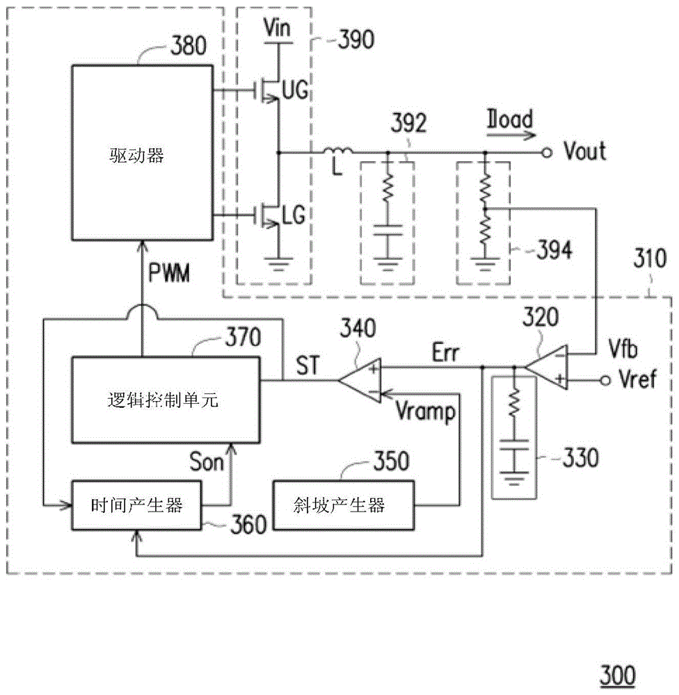
The invention provides a time generator and a time signal generation method for a power converter. The timing generator includes a critical voltage generating circuit and a timing generating unit. The threshold voltage generation circuit receives an error signal related to the output voltage of the power converter. The critical voltage generation circuit generates the critical voltage according to the error signal. The time generating unit generates a time signal according to the error signal, the threshold voltage and the control signal. The timing generation unit provides tracking signals. The width of the time signal is a time dependent on the time when the tracking signal moves away from the level of the error signal to the level of the threshold voltage.

Description

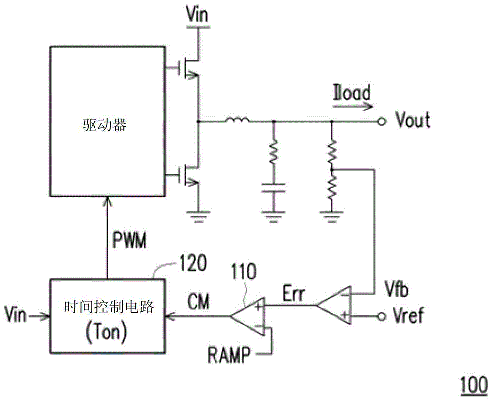
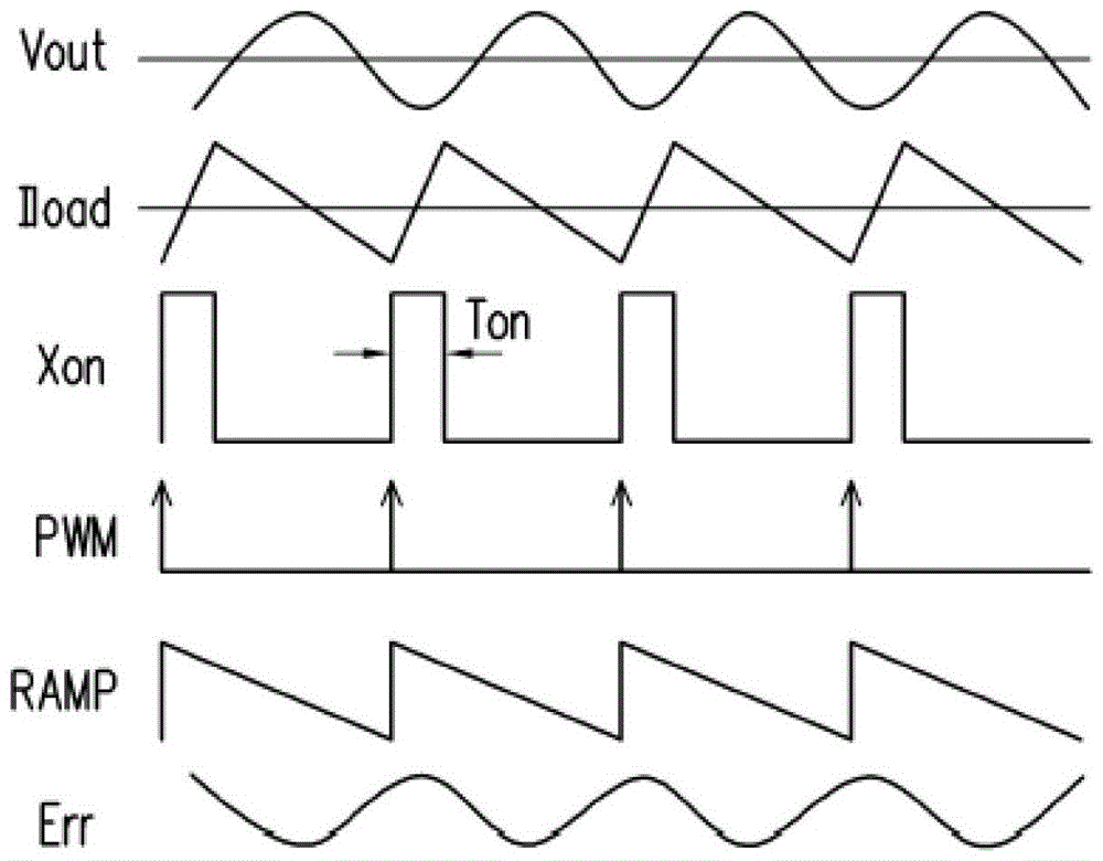
technical field [0001] The present invention relates to a power converter, and in particular to a time generator and a time signal generating method for the power converter. Background technique [0002] Existing DC-to-DC power supply designs often adopt a fixed on-time architecture. figure 1 is a schematic diagram of a conventional power converter 100 based on a constant on-time architecture. The comparator 110 compares the error signal Err with the ramp signal RAMP to generate the error signal CM, wherein the magnitude of the error signal Err is related to both the feedback signal Vfb and the reference voltage Vref. The time control circuit 120 uses a fixed on-time mechanism to generate an on-time signal for counting, and sets the pulse width modulation signal PWM according to the error signal CM, wherein the width of the on-time Ton is related to the input voltage Vin and the output voltage Vout related. [0003] figure 2 is a schematic diagram of waveforms in the po...

Claims


Application Information

Patent Timeline
Patent Type & Authority Patents(China)
IPC IPC(8): H02M1/088
CPCH02M3/156H02M3/1566H02M3/1563
Inventor 陈雅萍陈伟陵
Owner UPI SEMICON CORP
Why Eureka
Try Eureka