
System and method for establishing local control of a space conditioning load during a direct load control event

a technology for establishing local control and space conditioning, which is applied in the direction of instruments, heating types, static/dynamic balance measurement, etc., can solve the problems of increasing the cost of customer acquisition, and increasing the indoor temperature to a level that is uncomfortable for the customer, so as to restore the local control of the switch

Active Publication Date: 2013-01-08
ITRON
View PDF4 Cites 10 Cited by
  • Summary
  • Abstract
  • Description
  • Claims
  • Application Information

AI Technical Summary

Benefits of technology

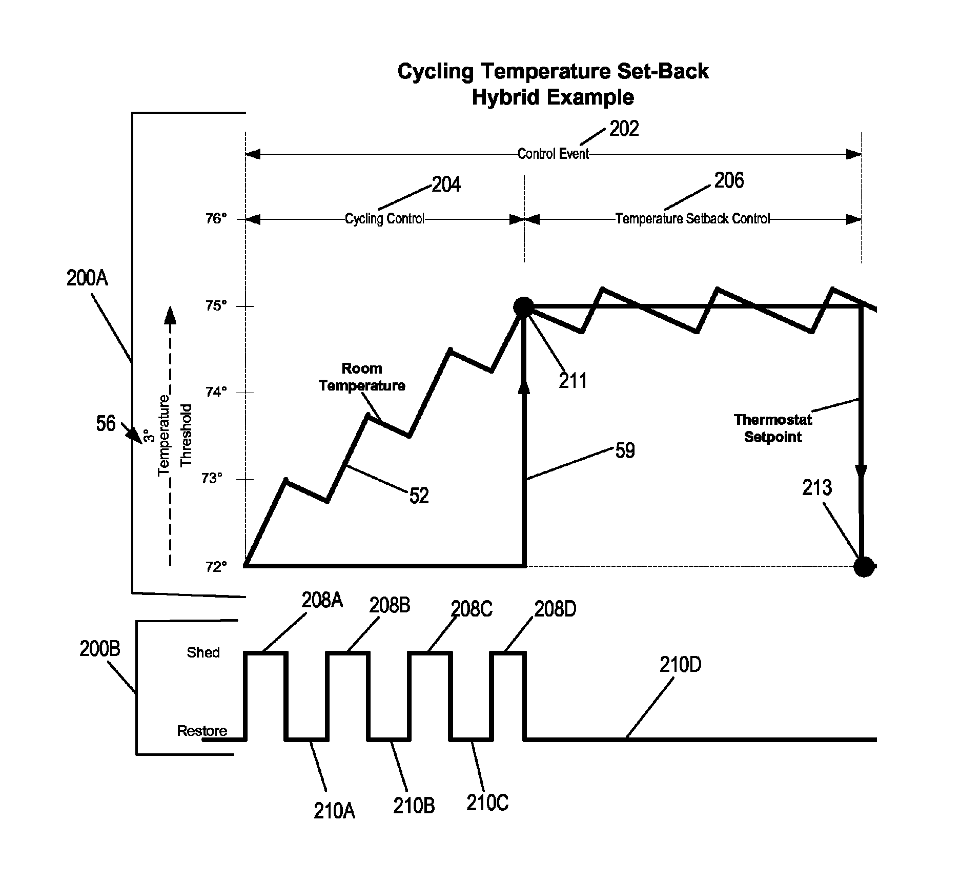
[0018]A system for establishing local control of a space conditioning load is also described and it may include a switch for controlling a flow of energy. The system also has control logic operatively coupled to the switch, for receiving one or more control parameters associated with a direct load control event from a communications network. The control logic may also measure room temperature based on received temperature signals and determine if a room temperature is one of greater than and equal to a comfort temperature range. The control logic may eliminate operation of a direct load control program associated with the one or more control parameters received if the room temperature is one of greater than and equal to a comfort temperature range. The control logic may then restore local control of the switch.

Problems solved by technology

Utility providers face the problem of satisfying consumer demand for electrical energy during peak and off-peak demand periods.
A problem associated with the cycling method is that the indoor temperature will usually continually rise during the control event and there is no temperature cap to limit this rise.
Depending on how long the control events lasts, on how well the home is insulated, and the outdoor temperature, the indoor temperature may raise to a level that is uncomfortable for the customer.
Customers may be more reluctant to sign up for cycling programs if the temperature rise during the event is too high or unknown, thus driving up the cost for customer acquisition and results in higher program costs.
Every degree of temperature setback usually results in some energy reduction from the HVAC system.
The problem with this solution is that the maximum and minimum temperature limits are set to be identical across all customers.
Using identical maximum and minimum temperature limits across all customers by a utility provider does not account for differences in the construction of the various spaces of the customers being serviced.
For example, a first building may be poorly insulated and may reach the maximum temperature on a hot day very quickly within an hour or two.
Similarly, a second building may be well insulated but its space conditioning load may be improperly sized for the space.
In this situation, the third building may not reach the maximum temperature on a hot day until several hours, significantly more than the first building with poor insulation and / or a poorly sized space conditioning load.
This reduces the energy reduction that the utility is seeking.
As noted above, if a building is poorly insulated and / or it has an improperly sized space conditioning load, the consumer will likely experience the maximum temperature quickly and frequently while the direct load control program is being executed.

Method used


Image

  • System and method for establishing local control of a space conditioning load during a direct load control event
  • System and method for establishing local control of a space conditioning load during a direct load control event
  • System and method for establishing local control of a space conditioning load during a direct load control event

Examples


Embodiment Construction

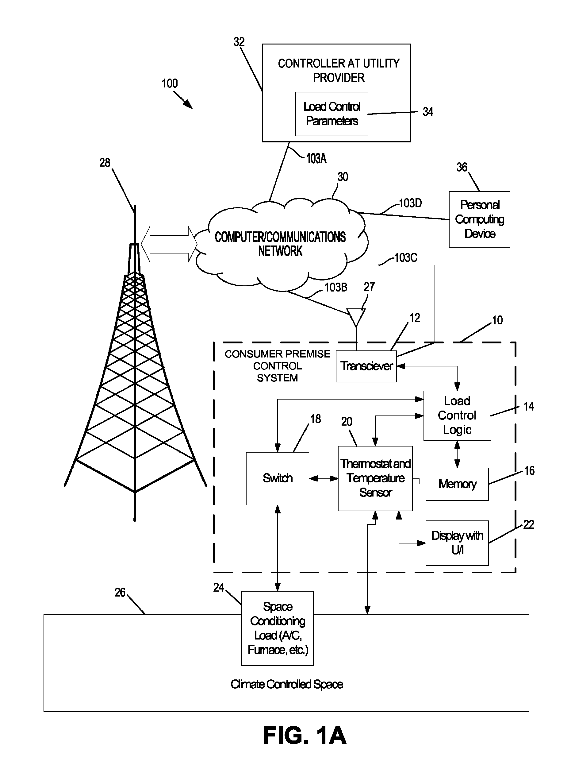
[0024]Referring initially to FIG. 1A, a diagram of a system 100 for establishing local control during a direct load control program is illustrated. The system 100 may include a customer premise control system 10, a space conditioning load 24, a climate controlled space 26, a wireless communications tower 28, a communications network 30, a controller 32 at a utility provider, and a personal computing device 36. Exemplary wireless communication networks that may employ wireless communications towers 28 or wireless environments in general include, but are not limited to, Advanced Metering Infrastructure (AMI) networks, Home Area Networks (HANs), any combination of the above, and other similar wireless communication networks. Many of the system elements illustrated in FIG. 1A are coupled via communications links 103A-D to the communications network 30.

[0025]The links 103 illustrated in FIG. 1A may comprise wired or wireless links. Wireless links include, but are not limited to, radio-fr...


PUM


Abstract

A system for establishing local control of a space conditioning load includes a switch for controlling a flow of energy for a space conditioning load. Control logic is operatively coupled to the switch, for receiving control parameters associated with a direct load control event from a utility provider. The control logic may also measure room temperature based on received temperature signals and determine if a room temperature is greater a comfort temperature range. The control logic may eliminate operation of a direct load control program if the room temperature is greater than or equal to the comfort temperature range. The control logic may log and signal back to the utility provider that the comfort temperature range is exceeded. The control logic may then restore local control of the switch and initiate a temperature setback control to a thermostat for the remainder of the control period.

Description

BACKGROUND[0001]Utility providers face the problem of satisfying consumer demand for electrical energy during peak and off-peak demand periods. Total electrical energy demand varies significantly between the peak and off-peak demand periods. For example, energy demand typically peaks on a hot summer afternoon as a result of the widespread simultaneous operation of air conditioning systems, and energy demand subsequently drops during the off-peak period of the late evening. To accommodate very high peak demands, utility providers face options of investing in additional power generating capacity, buying power from other utilities having excess capacity, or using an electrical load management system to control the amount of electrical energy distributed over the electrical distribution network during peak energy demand periods by electrical load reductions, commonly referred to as load shedding.[0002]As of this writing, many utility providers have turned to load shedding as the most vi...

Claims


Application Information

Patent Timeline
Patent Type & Authority Patents(United States)
IPC IPC(8): G05D23/00
CPCH02J3/14F24F11/00F24F11/0012F24F2011/0047F24F2011/0061F24F2011/0075Y02B70/3225Y02B70/3275Y04S20/222Y04S20/244F24F11/30F24F2110/10F24F2140/60F24F11/63F24F11/46H02J2310/12H02J2310/14Y02B70/30Y04S20/242F24F11/57F24F11/58F24F11/47F24F11/523
Inventor NG, HOWARD
Owner ITRON
Learn More