Navigation system, in-vehicle navigation apparatus and center apparatus

a navigation system and in-vehicle technology, applied in traffic control systems, navigation instruments, instruments, etc., can solve problems such as the in-vehicle navigation apparatus not calculating the rou

Active Publication Date: 2013-01-08
DENSO CORP
View PDF39 Cites 14 Cited by
  • Summary
  • Abstract
  • Description
  • Claims
  • Application Information

AI Technical Summary

Benefits of technology

[0010]Thus, the in-vehicle navigation apparatus does not calculate the route. Instead, the center apparatus calculates the route from the present position to the destination by searching the map data. When approaching the passing point included in the route, the in-vehicle navigation apparatus displays the received course information in superimposition on the forward image including the passing point in the travel direction. The route guide can be thus appropriately performed to follow an actual road state. In such a case, the in-vehicle navigation apparatus need not hold map data. The above configuration of the system thus helps prevent problems in costs and workloads resulting from an in-vehicle navigation apparatus holding map data.
[0013]Thus, the in-vehicle navigation apparatus does not calculate the route. Instead, the center apparatus calculates the route from the present position to the destination by searching the map data. When approaching the passing point included in the route, the in-vehicle navigation apparatus displays the course information obtained based on the vector information received from the center apparatus in superimposition on the forward image around the passing point in the travel direction. Thus, similarly with the first example, the route guide can be appropriately performed to follow actual road states. Also in the above configuration, the in-vehicle navigation apparatus need not hold map data. This helps prevent problems in costs and workloads resulting from an in-vehicle navigation apparatus holding map data.
[0016]Thus, if the navigation apparatus of the third example and the center apparatus of the fourth example are used cooperatively, similar advantages from the navigation system of the second example can be provided.

Problems solved by technology

Thus, the in-vehicle navigation apparatus does not calculate the route.

Method used


Image

  • Navigation system, in-vehicle navigation apparatus and center apparatus
  • Navigation system, in-vehicle navigation apparatus and center apparatus
  • Navigation system, in-vehicle navigation apparatus and center apparatus

Examples


first embodiment

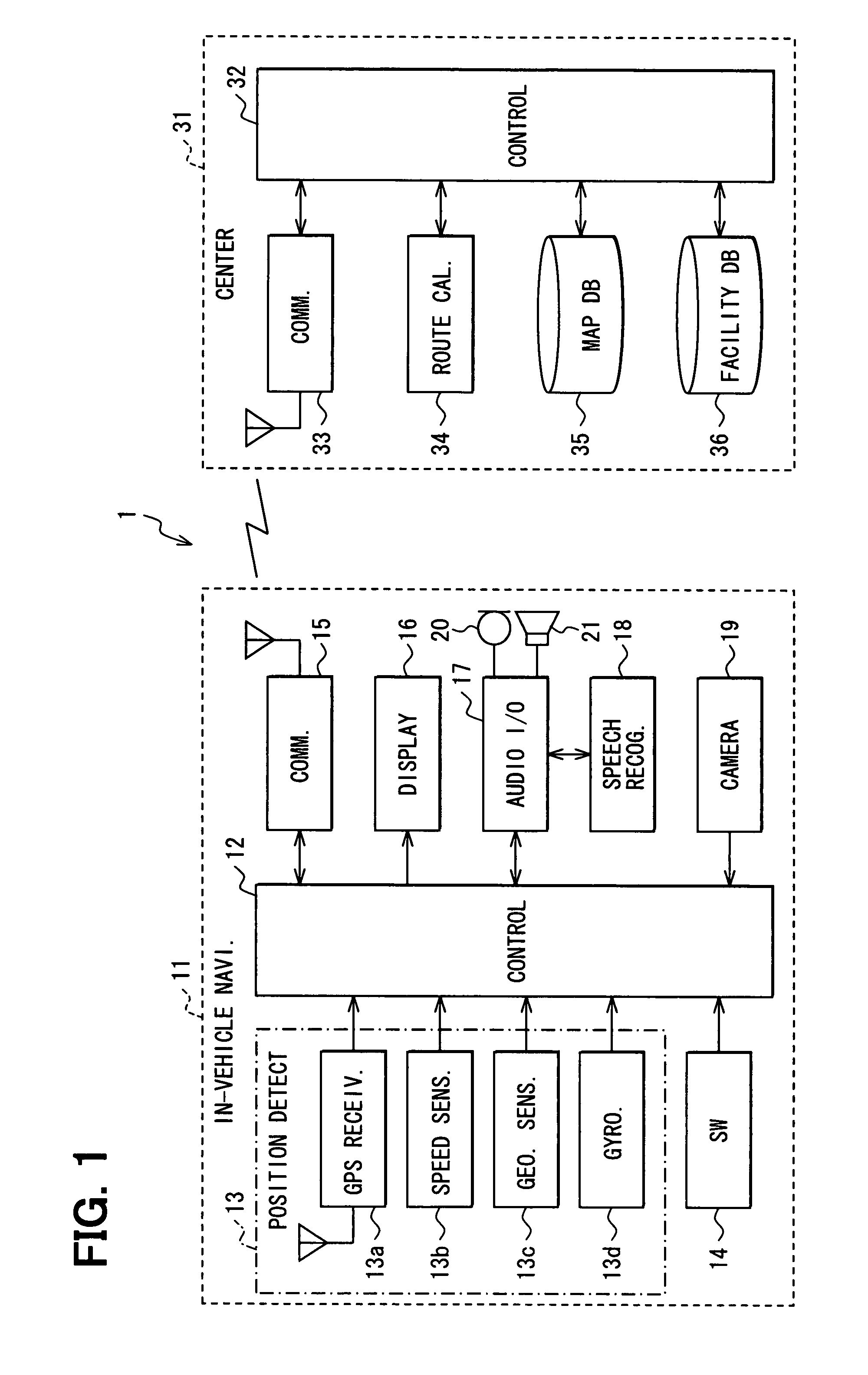
[0028]A first embodiment according to the present invention will be explained with reference to FIGS. 1 to 8. FIG. 1 illustrates an overall configuration of a communication type navigation system according to the first embodiment. The communication type navigation system 1 includes an in-vehicle navigation apparatus 11 mounted in a subject vehicle and a center apparatus 31 arranged in a center. The in-vehicle navigation apparatus 11 and the center apparatus 31 communicate with each other through a communication network (e.g., mobile phone network, fixed-line telephone network).

[0029]The in-vehicle navigation apparatus 11 includes the following: an in-vehicle control device 12 (which may function as a present position designation means or unit, or a destination designation means or unit); a position detection device 13; an operation switch 14; an in-vehicle communication device 15; a display device 16; an audio input / output device 17; a speech recognition device 18; and an in-vehicle...

second embodiment

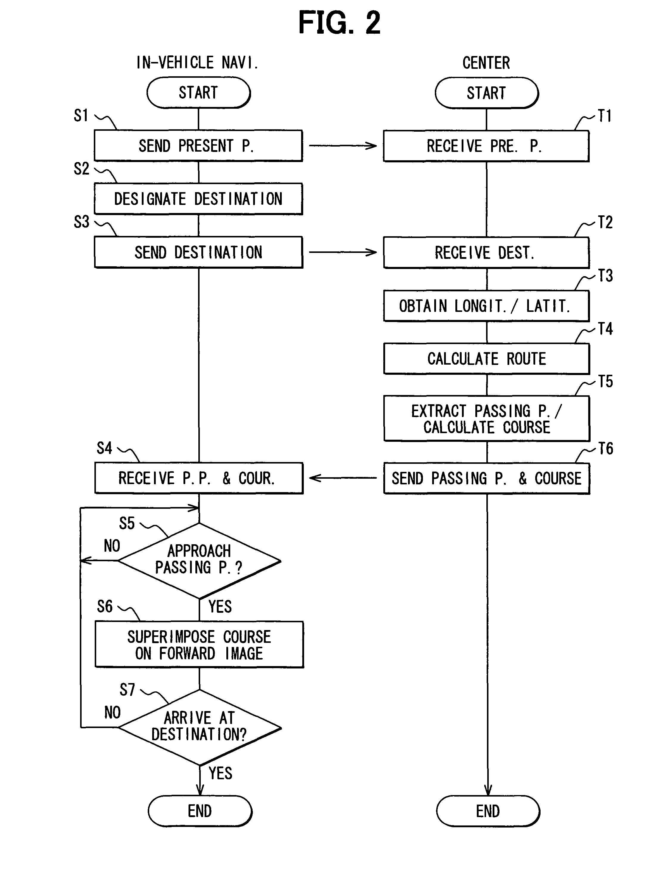
[0052]A second embodiment according to the present invention is explained with reference to FIGS. 9, 10. In addition, explanation is omitted for the same parts as those in the first embodiment and made for the different parts from the first embodiment. The center apparatus 31 of the second embodiment differs from that of the first embodiment in that vectors from the present position to the passing point and from the present position to the destination are further calculated while the passing point is similarly extracted from the route. That is, in the center apparatus 31, the control device 32 receives a present position (latitude and longitude) from the in-vehicle navigation apparatus 11 via the communication device 33 (Step T1). The control device 32 then receives a destination from the in-vehicle navigation apparatus 11 via the communication device 33 (Step T2). The latitude and longitude of the received destination are acquired (Step T3). As illustrated in FIG. 10, a route from ...


PUM


Abstract

In a communication type navigation system, a center apparatus receives a present position and destination from an in-vehicle navigation apparatus and thereby calculates a route by searching map data, which is constantly updated. The in-vehicle navigation apparatus receives the calculated route with course information from the center apparatus. When approaching a passing point included in the route, the navigation apparatus displays the course information in the travel direction in superimposition on a forward image around the passing point. The route guide can be thus appropriately performed to follow an actual road state. The above configuration of the system helps prevent problems in costs and workloads resulting from an in-vehicle navigation apparatus holding map data therein.

Description

CROSS REFERENCE TO RELATED APPLICATION[0001]This application is based on and incorporates herein by reference Japanese Patent Application No. 2006-325593 filed on Dec. 1, 2006.FIELD OF THE INVENTION[0002]The present invention relates to a navigation system, an in-vehicle navigation apparatus, and a center apparatus. The navigation system includes the foregoing two apparatuses, which communicate with each other via a communication network.BACKGROUND OF THE INVENTION[0003]An in-vehicle navigation apparatus holds or stores map data. When a destination is designated, the navigation apparatus calculates a route from a present position to the destination by searching the map data and superimposes the calculated route on a map displayed to thereby perform a route guide.[0004]Incidentally, road states constantly change by accompanying openings or closings of traffics in roads. The navigation apparatus is thus required to update the map data to match with the changes of the road states so th...

Claims


Application Information

Patent Timeline
Patent Type & Authority Patents(United States)
IPC IPC(8): G01C21/00G01C21/34G01C21/20G01C21/26
CPCG01C21/36G01C21/3647G08G1/0962
Inventor HAGIWARA, KAZUHIKO
Owner DENSO CORP
Why Eureka
Try Eureka