
Light guide with coupling portion having a plurality of reflective facets

a technology of reflective facets and light guides, applied in the direction of planar/plate-like light guides, lighting and heating apparatus, instruments, etc., can solve the problems of reducing the efficiency of a device of this type, reducing the performance of known devices, and reducing the efficiency of devices of this typ

Active Publication Date: 2013-01-15
VALEO VISION SA
View PDF17 Cites 1 Cited by
  • Summary
  • Abstract
  • Description
  • Claims
  • Application Information

AI Technical Summary

Benefits of technology

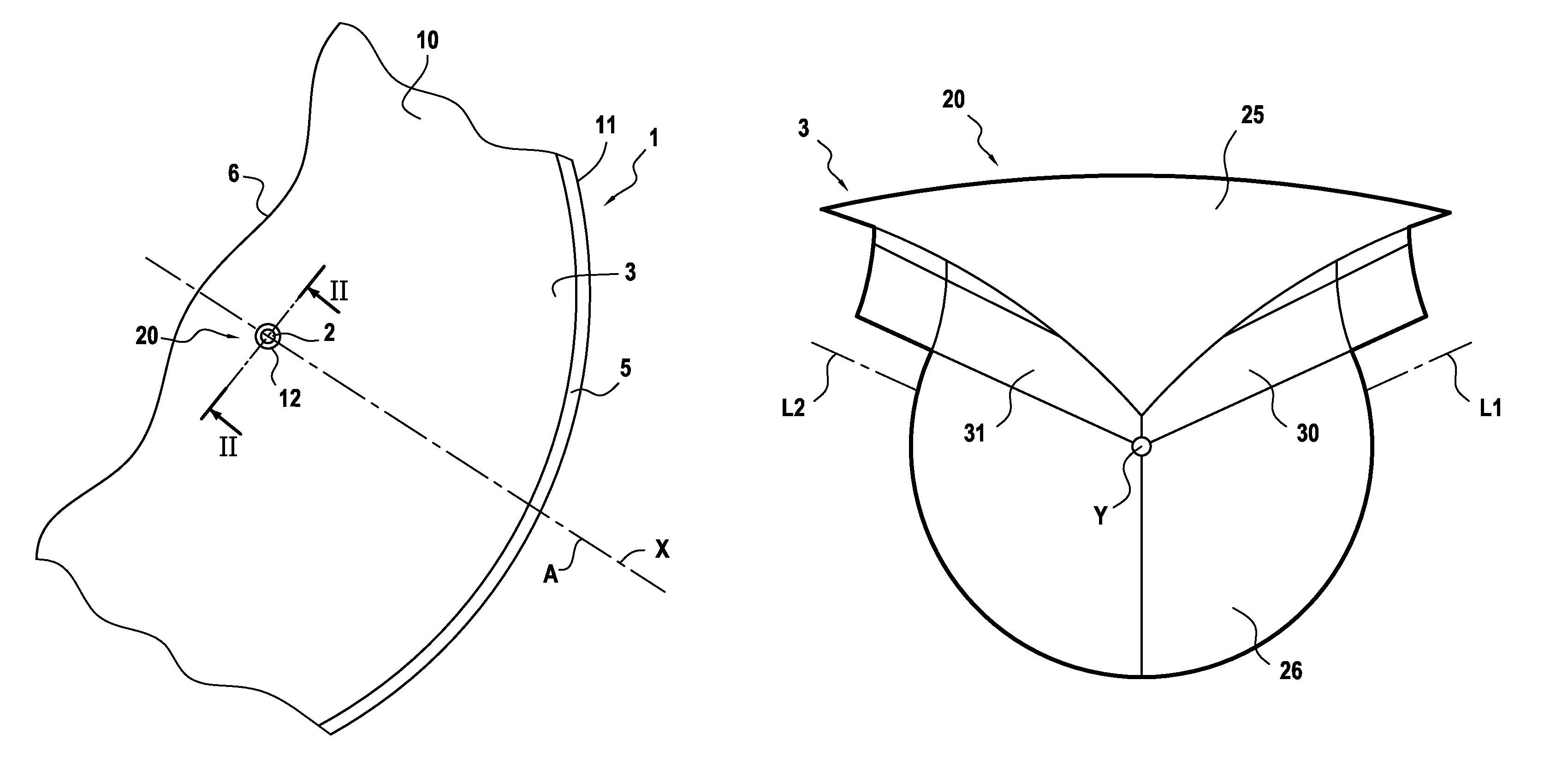
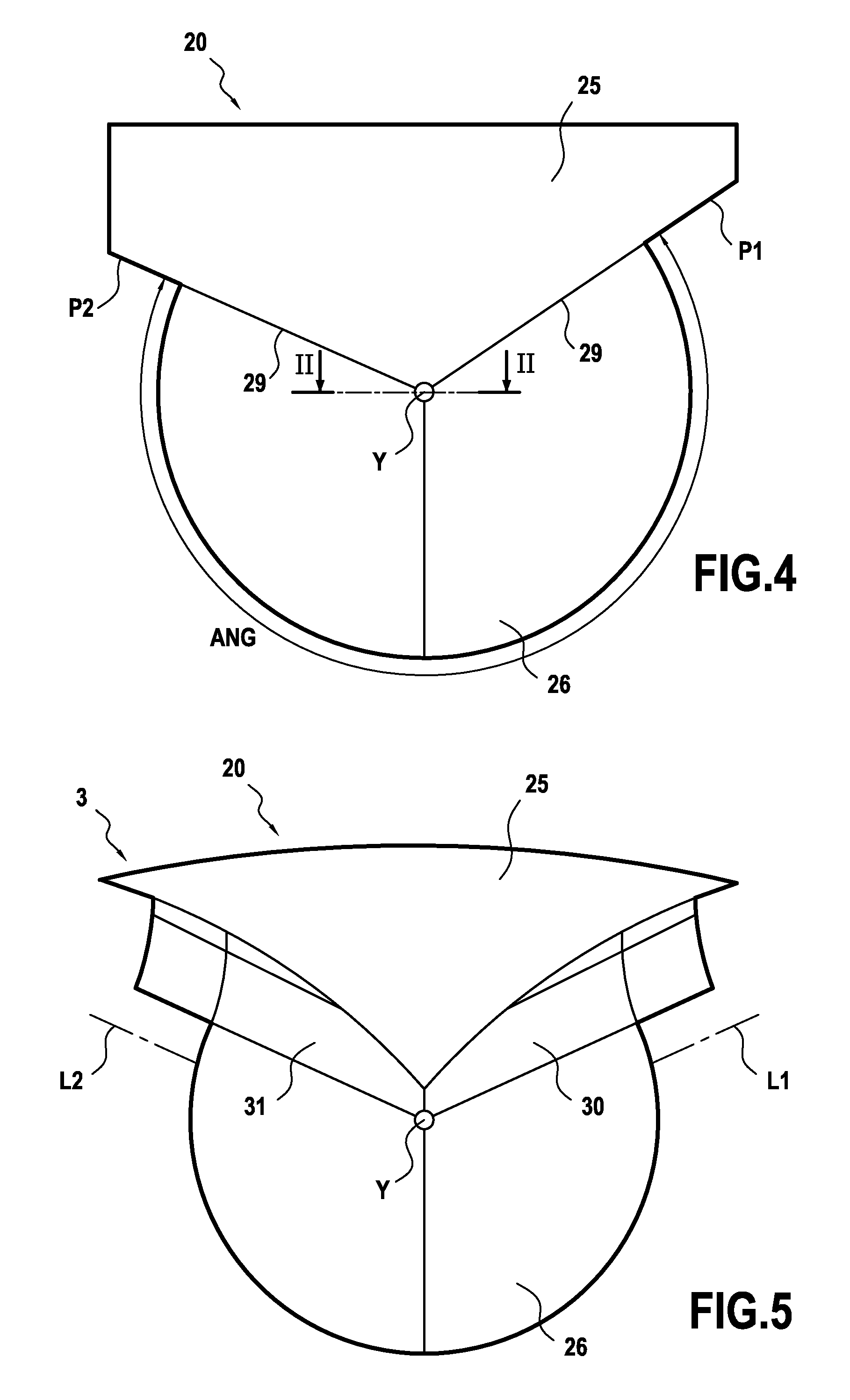
[0034]By means of the invention, the coupling portion of the light guide makes it possible to direct the light in selected directions, such that there is no, or little, photometric loss.
[0036]The coupling portion according to the invention makes it possible in particular to prevent certain rays of light from being directed towards the areas of the output surface, thus giving rise in an undesirable manner to reflection of the rays which prevents the latter from being emitted from the light guide, or to refraction of these rays in a direction which is inefficient for the performance of the output beam.
[0038]In addition, the invention makes possible improved homogeneousness, firstly because there is avoidance of an excessive quantity of direct light, which creates a hot spot when the light guide is seen from the sides, and secondly because the light is accumulated at the level of the end of the rear reflection surface, which makes it possible to balance better the quantity of light which is obtained from the edge of the rear reflection surfaces, in comparison with the quantity of light which is emitted by the base.
[0039]In addition, the invention can make it possible to prevent a lack of homogeneousness because of the presence of the source of light on the path of the rays of light, since the rays which are reflected by the areas of the reflection surface behind the source of light are partially hidden by the coupling portion.
[0053]This transition facet makes it possible to direct the rays of light towards the end limits of the rear reflection surface, then progressively towards the remainder of the rear surface, closer to the source of light.

Problems solved by technology

However, the efficiency of a device of this type is reduced when the rear surface does not surround the LED sufficiently.
Between these areas, the rays of light are either lost definitively, since they are reflected totally by the output surface, or they are refracted by the output surface towards excessively large angles which do not allow them to participate in the photometry of the beam.
Thus, the known device can be subject to relatively substantial losses of performance.

Method used


Image

  • Light guide with coupling portion having a plurality of reflective facets
  • Light guide with coupling portion having a plurality of reflective facets
  • Light guide with coupling portion having a plurality of reflective facets

Examples


Embodiment Construction

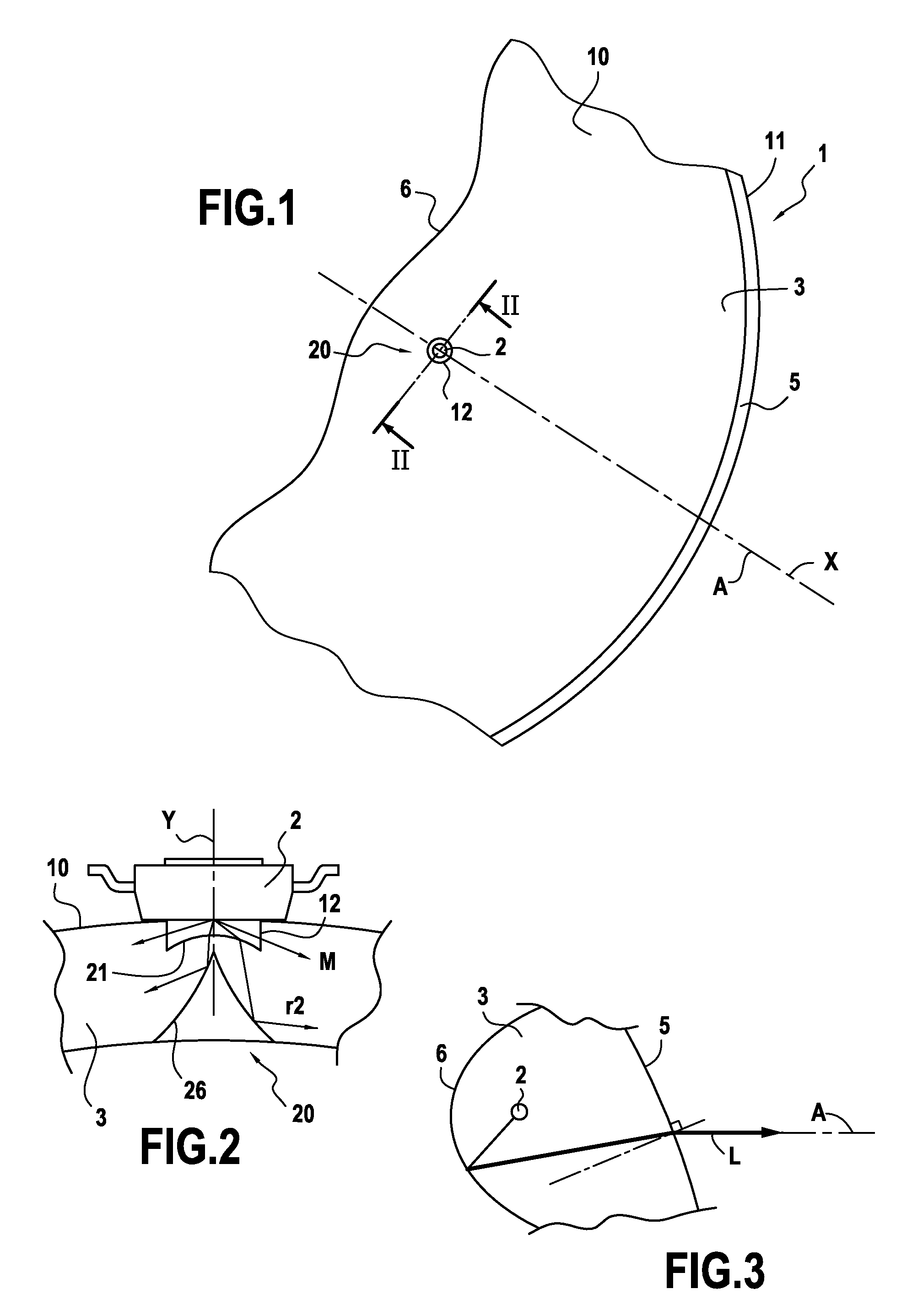
[0076]FIGS. 1 to 3 show an optical device 1 for a motor vehicle, such as a lighting or signaling device, comprising:

[0077]a source of light 2 which is formed by an LED of the Lambert, or axial emission type; and

[0078]a light guide 3 which is designed to guide the light emitted by the source of light 2, the light guide 3 comprising at least one output surface 5 and at least one reflection surface 6 which is designed to reflect towards the output surface 5 light L which is propagated in the guide 3.

[0079]The light guide 3 is in the form of a sheet with a longitudinal axis X, and has two main surfaces 10 and 11, for example, which are not flat, and are substantially parallel to one another.

[0080]The thickness of this light guide 3 measured between the two main surfaces 10 and 11 is, for example, contained between 3 mm and 5 mm.

[0081]The output surface 5 can comprise serrations to diffuse the light obtained from this surface 5.

[0082]In the example described, the light guide 3 is monolit...


PUM


Abstract

An optical device, in particular for a motor vehicle, such as a lighting or signaling device, this device comprising at least one light guide which is designed to guide at least part of the light which is emitted by a source of light, the light guide comprising at least one output surface and at least one main reflection surface, which is designed to reflect towards the output surface light which is propagated in the guide, the light guide comprising a portion for coupling with the source of light, this coupling portion having a transverse axis (Y), wherein the coupling portion is arranged such that the light which is emitted from this coupling portion is propagated in the light guide, around the transverse axis, according to a total angular opening, measured around this transverse axis, which is strictly less than 360°, and in particular is less than 320° or 300°.

Description

CROSS-REFERENCE TO RELATED APPLICATIONS[0001]This application claims priority to French Application No. 0901154 filed Mar. 12, 2009, which application is incorporated herein by reference and made a part hereof.BACKGROUND OF THE INVENTION[0002]1. Field of the Invention[0003]The invention relates to an optical device, in particular for a motor vehicle, such as a lighting or signaling device.[0004]2. Description of the Related Art[0005]A lighting or signaling device for a motor vehicle is known from patent application EP 1 881 263, which is equivalent to U.S. Patent Publication 2008 / 0019139 which is incorporated herein by reference and made a part hereof. The lighting device can emit a light beam “F” according to a longitudinal optical axis “A”.[0006]This optical device comprises at least one sheet for guiding the light, at least one part of which is in the form of a portion of spherical cap.[0007]The guide sheet is thus delimited in the direction of the thickness by two guide surfaces...

Claims


Application Information

Patent Timeline
Patent Type & Authority Patents(United States)
IPC IPC(8): F21V7/04
CPCF21S48/1241F21S48/2268G02B6/002G02B6/0018G02B6/0055F21S41/24F21S43/245
Inventor DE LAMBERTERIE, ANTOINE
Owner VALEO VISION SA
Learn More