Electrical connector

Inactive Publication Date: 2013-01-15
CHENG UEI PRECISION IND CO LTD
View PDF5 Cites 16 Cited by
  • Summary
  • Abstract
  • Description
  • Claims
  • Application Information

AI Technical Summary

Benefits of technology

The patent text describes a shielding cover that is connected to ground and placed on the front of an insulating housing to protect against external electromagnetic interference. The cover has contact strips that filter out external interference and are arranged around the edges of the housing. This results in an effective prevention of electromagnetic interference in the electrical connector.

Problems solved by technology

However, the metal shell is generally designed with an evenness outer structure that generally realizes a poor effect for filtering external electromagnetic interference.
As a result, electromagnetic interference is often apt to happen in the electrical connector to affect signal communication between the electronic product and the peripheral device thereof.

Method used


Image

  • Electrical connector
  • Electrical connector
  • Electrical connector

Examples


Embodiment Construction

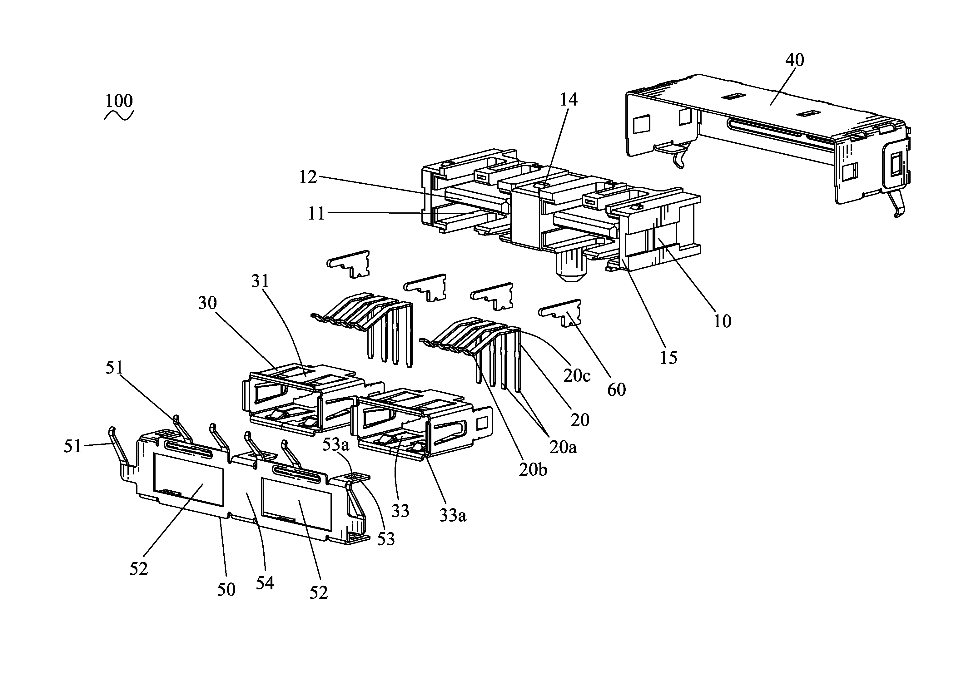
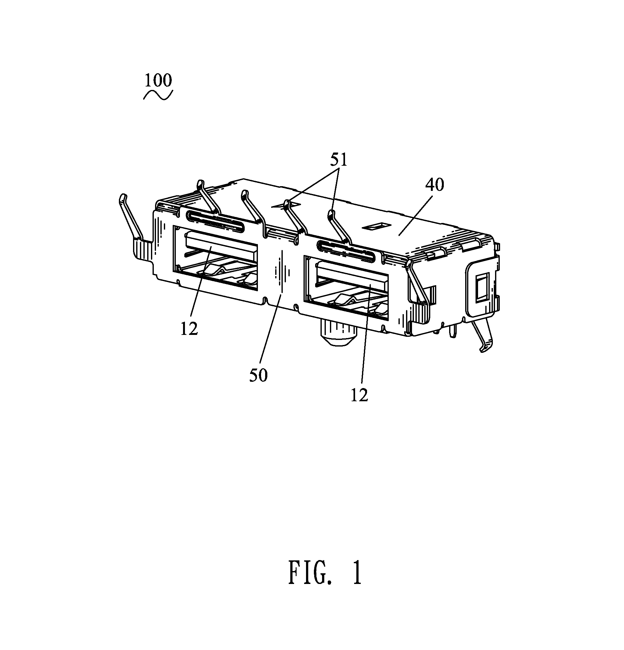
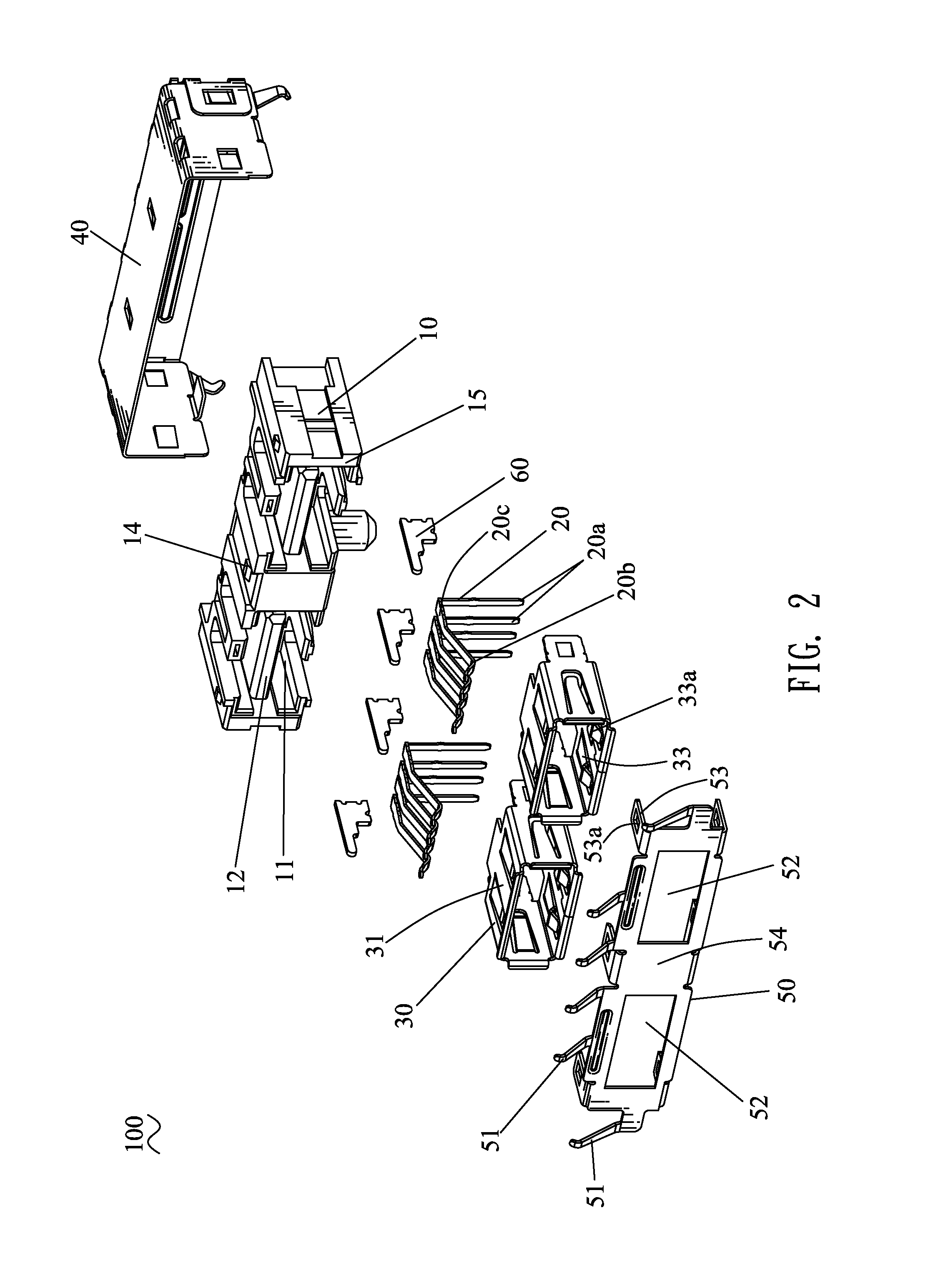
[0013]Referring to FIG. 1 and FIG. 2, an electrical connector 100 in accordance with an embodiment of the present invention includes an insulating housing 10, a plurality of electrical terminals 20, two holding shells 30, a shielding shell 40 and a shielding cover 50.

[0014]Referring to FIG. 2 and FIG. 5, the insulating housing 10 is of a substantially rectangular shape, and has a front surface 15 concaved rearward to apart define two receiving chambers 11 of rectangular ring shape seen from a front view. Accordingly, a rectangular tongue board 12 is formed in the middle of each receiving chamber 11. A front end of each receiving chamber 11 is opened freely for the convenience of insertion of a mating connector (not shown). A bottom side of the tongue board 12 defines a plurality of terminal fillisters 13 arranged at regular intervals along a transverse direction thereof, and each extending longitudinally to further penetrate rearward through the insulating housing 10.

[0015]Referring...


PUM


Abstract

An electrical connector includes an insulating housing having a front surface concaved rearward to define a receiving chamber with a tongue board therein. Electrical terminals are disposed in the tongue board and elastically stretch into the receiving chamber. A frame-shaped holding shell is mounted in the receiving chamber. A shielding cover adapted for being connected to ground and punched from a metal board has a base board with a window being opened therein and a plurality of contact strips being formed and apart arranged to periphery edges of the base board. The base board is covered onto the front surface of the insulating housing with the window being communicated with the receiving chamber. The contact strips stretch freely outside the insulating housing. A shielding shell is put around the insulating housing and electrically connected with the shielding cover.

Description

BACKGROUND OF THE INVENTION[0001]1. Field of the Invention[0002]The present invention relates to an electrical connector, and more particularly to an electrical connector capable of shielding electromagnetic interference.[0003]2. The Related Art[0004]With fast development of electronic technology, various electronic products and peripheral devices thereof are connected with each other with increasing frequency. So, an electrical connector is often used to achieve the connection between the electronic products and the peripheral devices thereof. The rapid developments of the electrical connector call for more stringent requirement to electromagnetic shielding effect of the electrical connector. A traditional method for shielding electromagnetic interference in the electrical connector is to utilize a metal shell to connect with ground. However, the metal shell is generally designed with an evenness outer structure that generally realizes a poor effect for filtering external electroma...

Claims


Application Information

Patent Timeline
IPC IPC(8): H01R9/03
CPCH01R13/6581H01R25/006
Inventor LAN, RONG-QINXU, LI-JUNLIN, MING-HAN
Owner CHENG UEI PRECISION IND CO LTD
Why Eureka
Try Eureka