Mixing element for a static mixer and process for producing such a mixing element

a technology of mixing element and mixer, which is applied in the direction of mixers, coatings, chemical/physical/physical-chemical processes, etc., can solve the problems of reducing affecting the mixing quality of the mixer, and complicated manufacturing of the mixer insert, etc., and achieves the effect of good control

Inactive Publication Date: 2013-01-29
STAMIXCO
View PDF34 Cites 19 Cited by
  • Summary
  • Abstract
  • Description
  • Claims
  • Application Information

AI Technical Summary

Benefits of technology

[0011]In a preferred design, the mixer insert is arranged in a container with projecting supports, with the longitudinal supports of the mixer insert lying on the supports of the container so that the forces acting on the mixer insert are transmitted to the container at defined positions. This arrangement likewise reduces the danger that the mixer insert could be deformed. This arrangement has, moreover, the advantage that all connection points have a common form which is favorable flow-wise because the starting parts can, for example, be cast from an easily fusible material such as wax by means of a tool, the mixer insert can be removed in simple manner from the container, its open structure can be more simply and quickly cleaned and for example can be controlled well, or indeed replaced.
[0012]The mixer insert in accordance with the invention has moreover the advantage that it does not have any significant flow obstacles such as large, bulky or misshapen welding points to which the fluids, in particular viscous fluids, could stick during the throw-flow. In this way it is precluded that fluids dwell for a long time at the same point and could indeed decompose, for example with temperature-sensitive polymers.

Problems solved by technology

A disadvantage of this mixer is the fact that the manufacture of the mixer insert is very complicated and thus costly.
A disadvantage is moreover the fact that the mixer insert has ribs at its periphery extending in the longitudinal direction to the tube wall which serve to reinforce the mixer in the axial direction against the pressure drop forces which likewise occur in the axial direction along which a medium to be mixed can flow in the axial direction unhindered through the boundary regions in which the longitudinal ribs extend which considerably reduces the mixing quality of the mixer.

Method used


Image

  • Mixing element for a static mixer and process for producing such a mixing element
  • Mixing element for a static mixer and process for producing such a mixing element
  • Mixing element for a static mixer and process for producing such a mixing element

Examples


Embodiment Construction

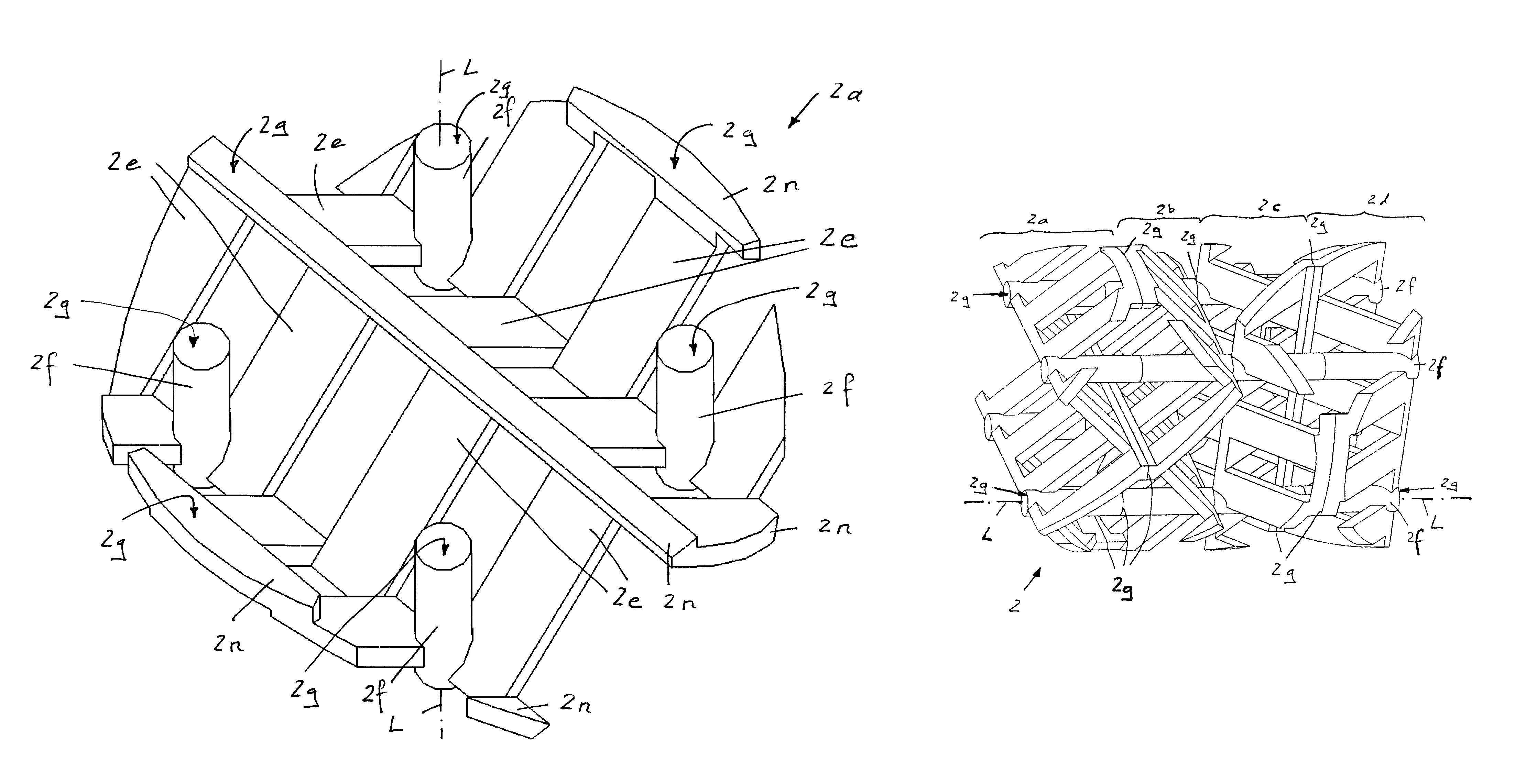
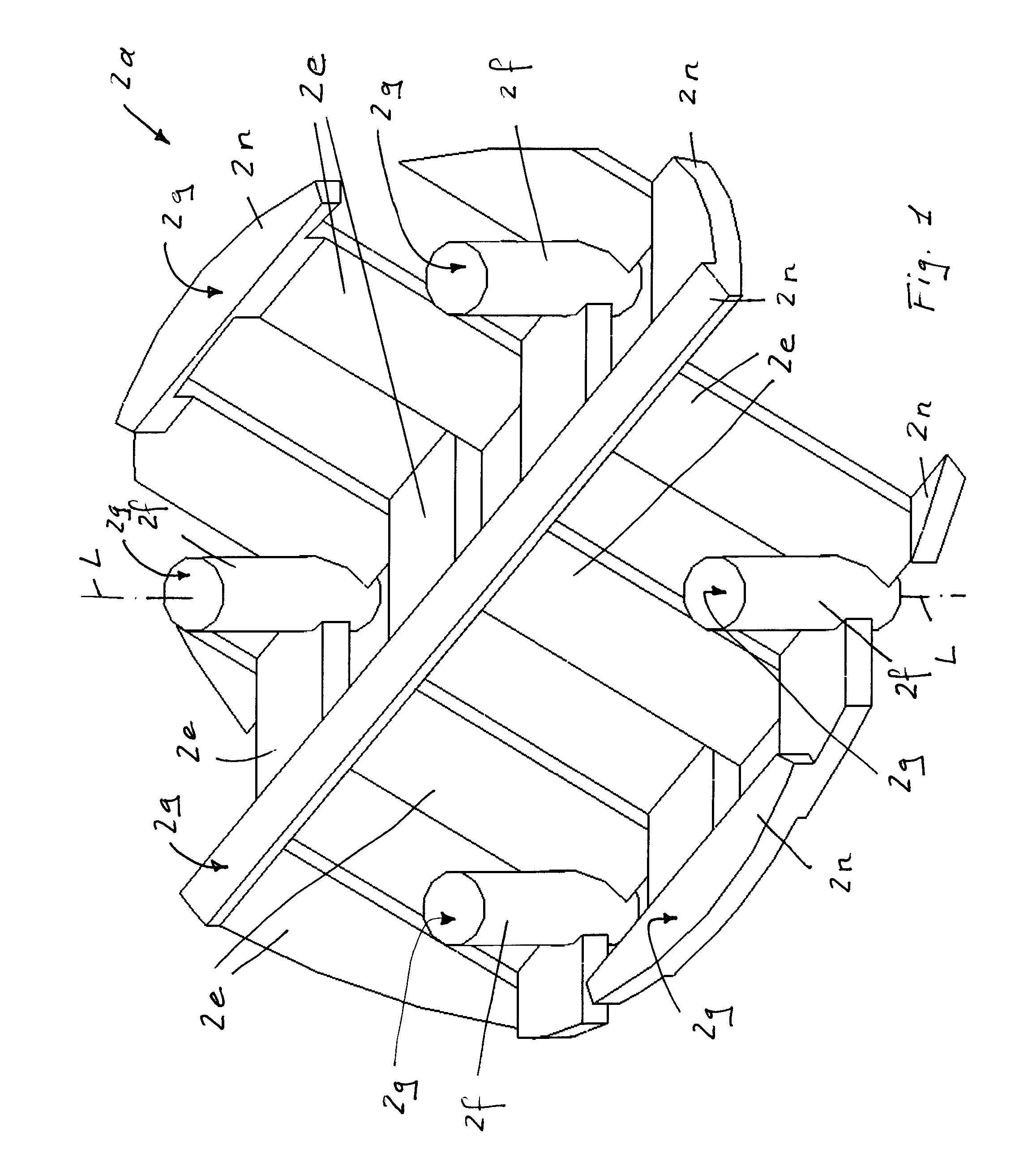
[0024]FIG. 1 shows a basic element 2a having four longitudinal supports 2f extending in the longitudinal direction L, with each longitudinal support having, at each of its two end portions, a respective contact surface 2g extending perpendicular to the longitudinal direction L and also forming a point of contact 2g to a basic element 2a arranged lying next to it. All longitudinal supports 2f are of the same length. The basic element 2a has a plurality of bars 2e extending transverse to the longitudinal direction L.

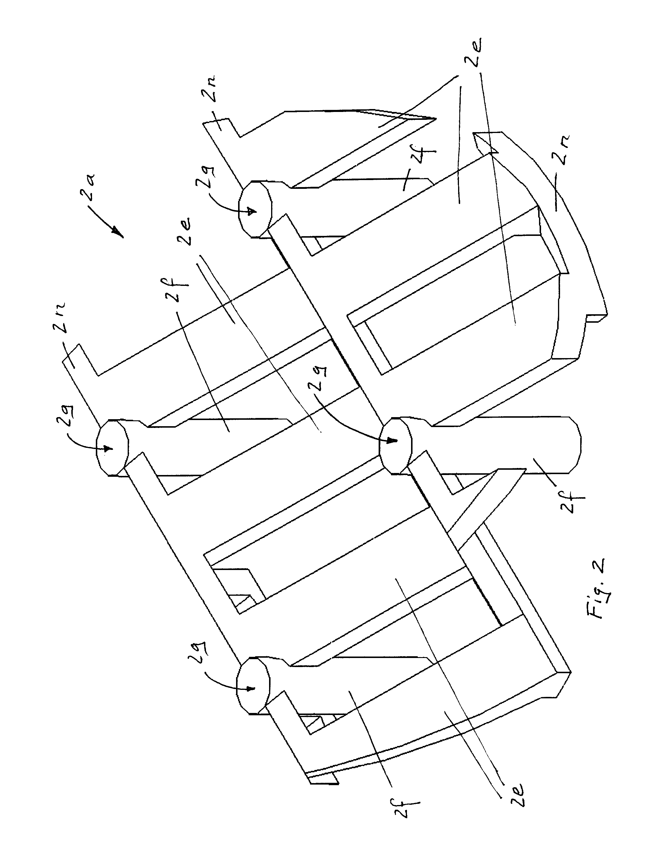
[0025]FIG. 2 shows the opposite side of the basic element 2a shown in FIG. 1. The same reference numerals represent the same elements.

[0026]FIG. 3 shows the basic element 2a shown in FIG. 2 in a side view. The bars 2e extend with respect to the longitudinal direction L at an angle α of less than 90 degrees, that is to say transverse to the longitudinal direction L, preferably at an angle α in the range between 10 degrees and 80 degrees. The basic element 2a has five connec...


PUM

PropertyMeasurementUnit
angleaaaaaaaaaa
angleaaaaaaaaaa
angleaaaaaaaaaa

Abstract

The mixer insert (2) for a static mixer (1) extends in one longitudinal direction (L), the mixer insert (2) having a multitude of elements (2e) running transverse to the longitudinal direction (L) and at least two longitudinal supports (2f) running in longitudinal direction (L), and the static mixer insert (2) consisting of a multitude of base elements (2a, 2b, 2c, 2d) arranged alongside one another in longitudinal direction (L), each base element (2a, 2b, 2c, 2d) comprising a longitudinal support (2f), and the base elements (2a, 2b, 2c, 2d) and their longitudinal supports (2f) being arranged relative to one another such that a longitudinal support (2f) running over the entire length of the mixer insert (2) is present, and base elements (2a, 2b, 2c, 2d) arranged alongside one another are bonded to one another in a fixed manner at least via the longitudinal supports (2f).

Description

FIELD OF THE INVENTION[0001]The invention relates to a mixer insert for a static mixer and methods of manufacture therefore.BACKGROUND OF THE INVENTION[0002]The document EP 0727249 discloses a static mixer for the mixing of highly viscous media. The static mixer includes a tube and also a mixer insert arranged within the tube. The mixer insert is also termed a mixing element. A disadvantage of this mixer is the fact that the manufacture of the mixer insert is very complicated and thus costly. A disadvantage is moreover the fact that the mixer insert has ribs at its periphery extending in the longitudinal direction to the tube wall which serve to reinforce the mixer in the axial direction against the pressure drop forces which likewise occur in the axial direction along which a medium to be mixed can flow in the axial direction unhindered through the boundary regions in which the longitudinal ribs extend which considerably reduces the mixing quality of the mixer.SUMMARY OF THE INVENT...

Claims


Application Information

Patent Timeline
Patent Type & Authority Patents(United States)
IPC IPC(8): B01F5/06
CPCB01F5/0619B01F15/00935B29B7/325B01F2215/0049B01F25/43161B01F35/561B01F2101/2805
Inventor SCHNEIDER, GOTTLIEB
Owner STAMIXCO
Why Eureka
Try Eureka