Oil pump rotor

a technology of oil pump and rotor, which is applied in the direction of liquid fuel engines, rotary piston liquid engines, machines/engines, etc., can solve the problems of increased size and weight or friction, increased noise, and increased pulsation, and achieve the effect of facilitating the formation of an outer rotor

Active Publication Date: 2013-01-29
AISIN SEIKI KK
View PDF34 Cites 7 Cited by
  • Summary
  • Abstract
  • Description
  • Claims
  • Application Information

AI Technical Summary

Benefits of technology

[0011]The present invention was made to address the problems described above and its object is to provide an oil pump rotor in which the discharge rate is increased while reducing pulsation and noise level without increasing the rotor size.
[0013]This makes it possible to increase the discharge rate without increasing the rotor size, and to provide an oil pump rotor with reduced pulsation and noise level.
[0017]This allows further reduction in the pulsation in oil discharged from the oil pump by making uniform the clearance between the addendum of the inner rotor and the outer rotor.
[0025]This makes it possible to increase the discharge rate while maintaining the rotor radius, and to provide an oil pump rotor with reduced pulsation and noise level.
[0036]This facilitates forming an outer rotor that meshes smoothly with an inner rotor that is formed by applying a deformation in the circumferential direction and a deformation in the radial direction to a tooth profile defined by the mathematical curve, or by applying a compressing deformation in the circumferential direction to the profile.

Problems solved by technology

While it is common to reduce the number of teeth to increase the discharge amount of the oil pump, since the discharge amount per cell increases in an oil pump with a small number of teeth, the pulsation becomes more pronounced and there was the problem of noise due to vibration of pump housing etc.
And, in order to secure the required amount of discharge, either the outside radius of the rotor or the thickness needs to be increased, which results in problems such as increased size and weight or friction.Patent Document 1: Japanese Patent Application Publication No. 2005-076563Patent Document 2: Japanese Patent Application Publication No.

Method used


Image

  • Oil pump rotor
  • Oil pump rotor
  • Oil pump rotor

Examples


Embodiment Construction

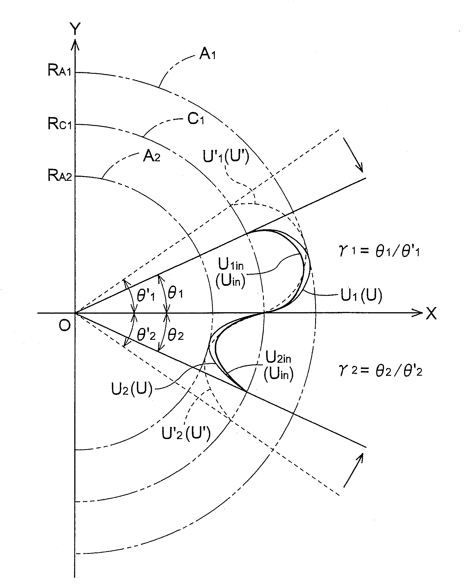
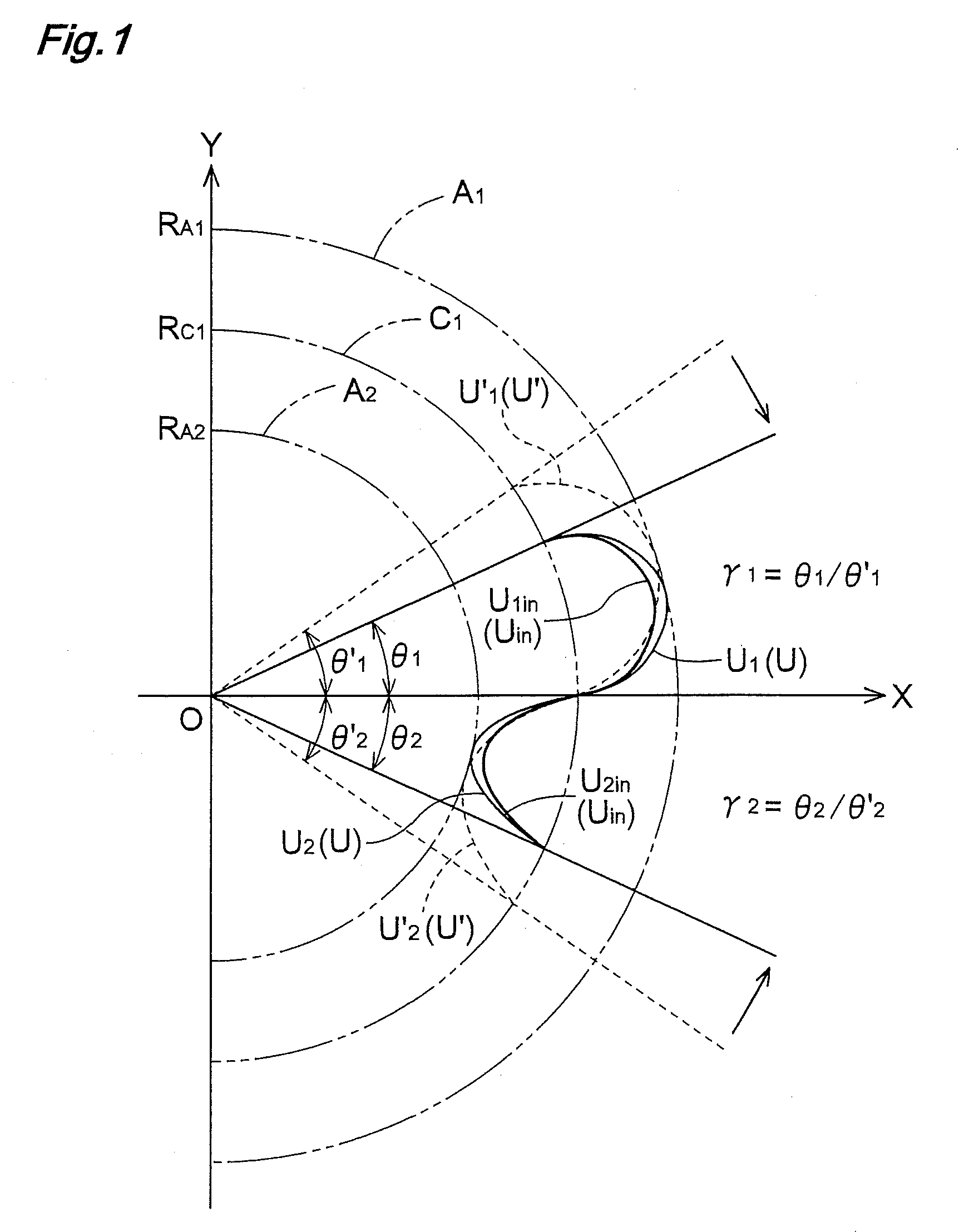
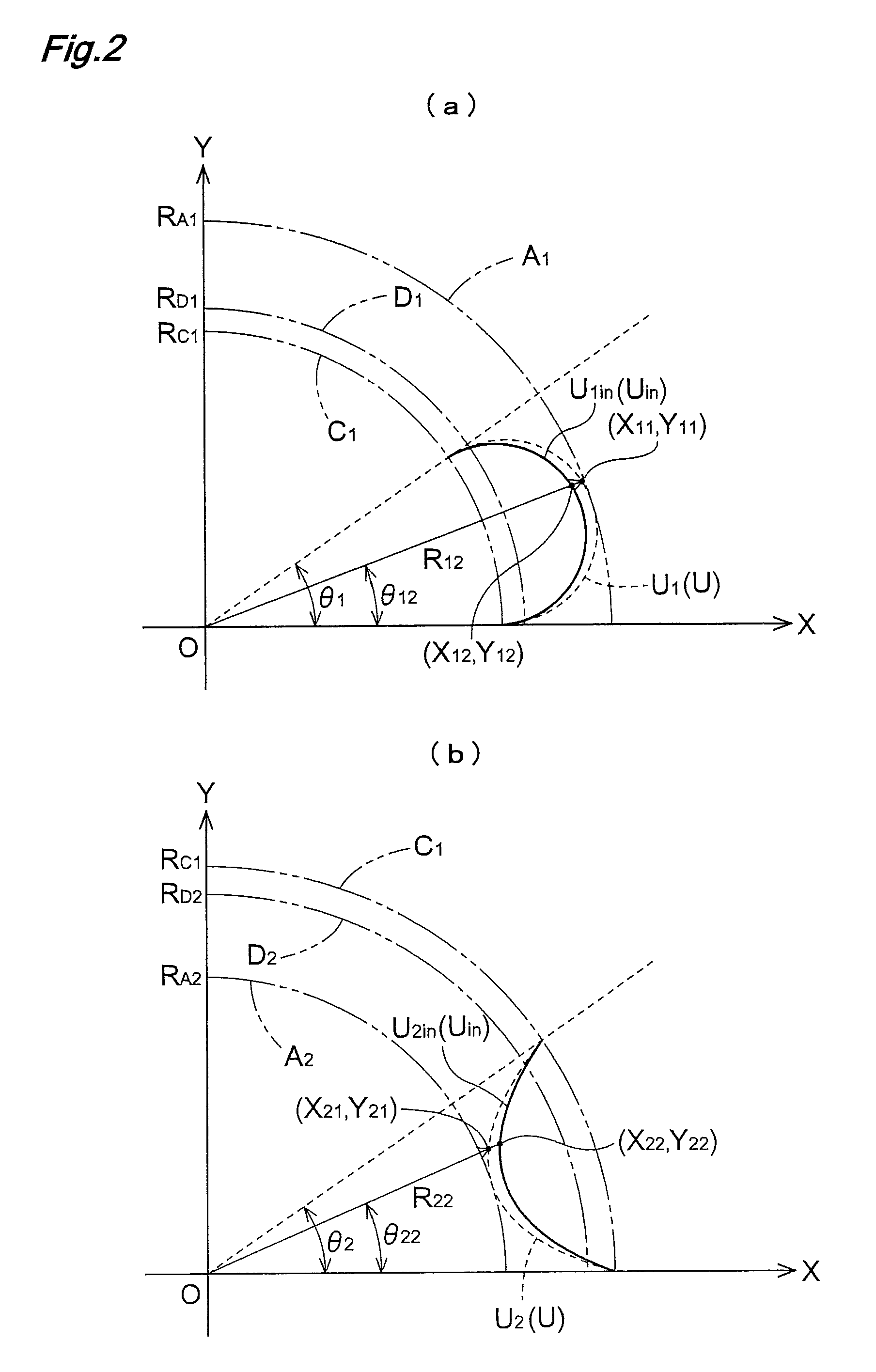
[0050]FIGS. 1 and 2 are diagrams showing the principle of a process for forming the tooth profile (external tooth profile) of the inner rotor in accordance with the present invention by applying a deformation in the circumferential direction and a deformation in the radial direction to a mathematical curve. While the addendum portion and tooth groove portion of only one tooth among the external teeth formed in the inner rotor are shown in FIGS. 1 and 2 without showing other gear teeth, the same deformation is naturally applied to all the gear teeth.

[0051]FIG. 1 shows the deformation in the circumferential direction applied to the tooth profile defined by a mathematical curve. The shape of the addendum U′1and the shape of the tooth groove U′2 of the tooth profile U′ defined by the mathematical curve are shown in FIG. 1 by the dotted line, and the radius of the addendum circle A1 in which the shape of the addendum U′1 is inscribed is denoted by RA1 and the radius of the tooth groove c...


PUM


Abstract

An oil pump rotor includes an inner rotor formed with n (n: a natural number) external teeth, and an outer rotor formed with n+1 internal teeth which are in meshing engagement with each of the external teeth. And the oil pump rotor is used in an oil pump that includes a casing having a suction port for drawing in fluid and a discharge port for discharging fluid and conveys the fluid by drawing in and discharging the fluid due to changes in volumes of cells formed between surfaces of the internal teeth and surfaces of the external teeth during rotations of the rotors under meshing engagement therebetween. And the tooth profile of the external teeth of the inner rotor is formed by a deformation in the circumferential direction and a deformation in the radial direction applied to a profile defined by a mathematical curve with the deformation in the circumferential direction is applied while maintaining the distance between the radius (RA1) of an addendum circle (A1) and the radius (RA2) of the tooth groove circle (A2).

Description

TECHNICAL FIELD[0001]The present invention relates to an oil-pump rotor which draws in and discharges fluid through changes in the volumes of cells formed between an inner rotor and an outer rotor.BACKGROUND ART[0002]A conventional oil pump has an inner rotor formed with n external teeth where n is a natural number, an outer rotor formed with n+1 internal teeth that mesh with the external teeth, and a casing with an suction port which draws in fluid and a discharge port which discharges fluid. The outer rotor is rotated by rotating the inner rotor with the external teeth meshed with the internal teeth, which causes the volumes of a plurality of cells formed between the rotors to change to draw in or discharge the fluid.[0003]The cells are individually separated by the virtue of the fact that external teeth of the inner rotor and internal teeth of the outer rotor contact at forward and rearward positions with respect to the rotating direction respectively, and of the fact that the bo...

Claims


Application Information

Patent Timeline
Patent Type & Authority Patents(United States)
IPC IPC(8): F03C4/00F04C2/00
CPCF04C2/102
Inventor NUNAMI, KOJIONO, HISASHI
Owner AISIN SEIKI KK
Why Eureka
Try Eureka