Catheter air management system

a technology of catheter air and management system, applied in the field of catheter air management system, can solve the problems of reducing the effective operating time, not attractive, and affecting the effect of pressure monitoring catheters in low or negative pressure environments

Active Publication Date: 2013-01-29
IRRAS USA INC
View PDF22 Cites 21 Cited by
  • Summary
  • Abstract
  • Description
  • Claims
  • Application Information

AI Technical Summary

Benefits of technology

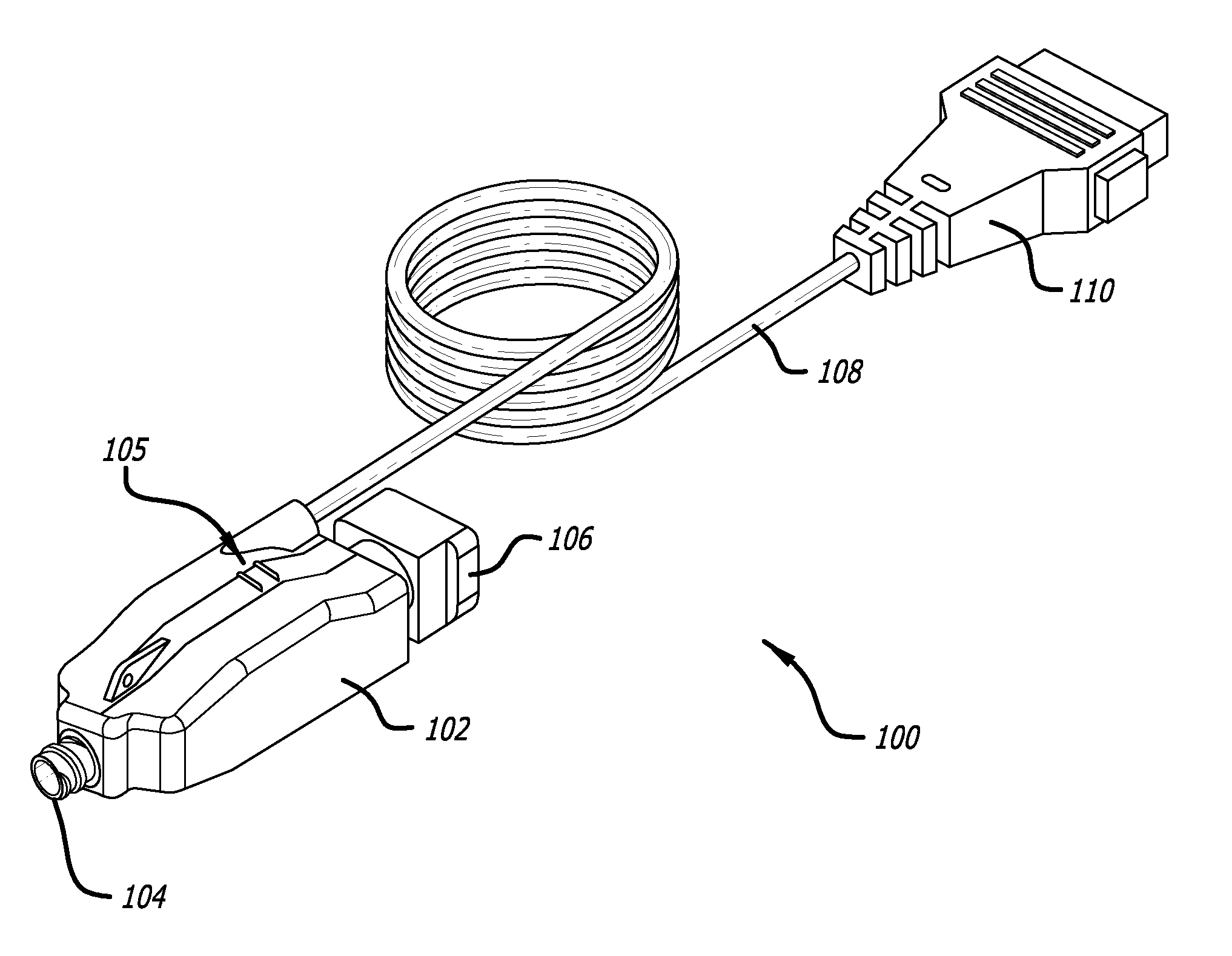
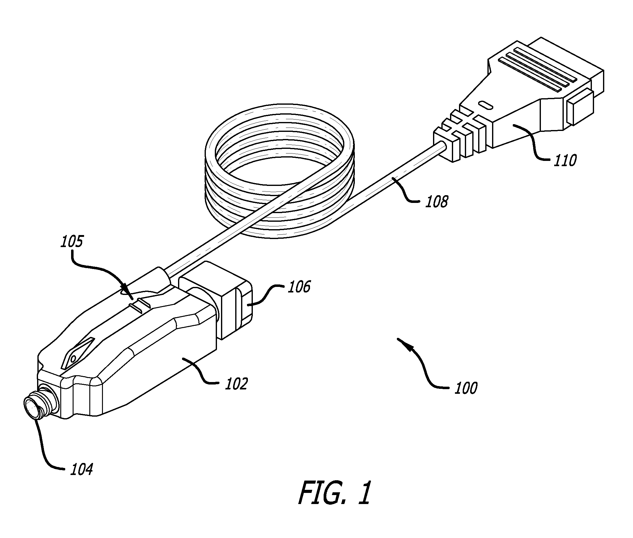
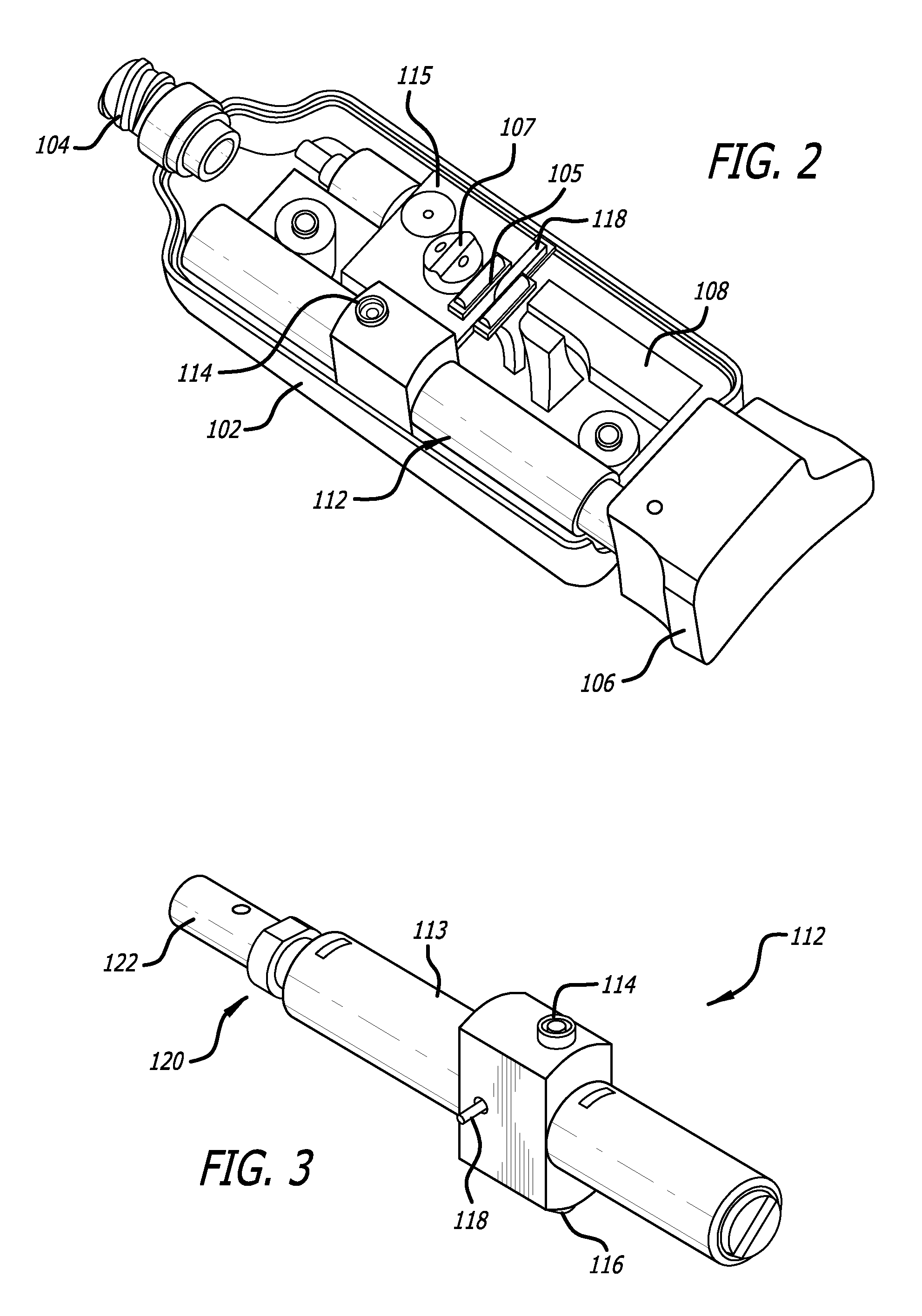
[0006]A preferred embodiment according to the present invention includes an air management system for removing and reintroducing a desired amount of air into an air passage of a pressure measurement catheter. More specifically, the system includes three cylinders within which can move a shaft with three sealing members along its length. The system includes check valves in communication with one of the cylinders. As the shaft is moved within the set of cylinders, it causes the residual air in the catheter air passage to be evacuated to a negative pressure defined by one check valve. Further movement of the piston member injects a predetermined volume of air into the catheter air passage. This air is from excess air present in the evacuation cylinder and held by a check valve at a predetermined pressure (e.g., 0.5 PSI), not from exposure to the open atmosphere. Evacuating the catheter to a fixed negative pressure prior to injecting air eliminates the possibility that variations in the residual volume in the bladder can affect the pressure reading or the operating time.

Problems solved by technology

The use of air-based pressure monitoring catheters in low or negatively pressurized environments has proven problematic.
While these systems function adequately when residual air in the bladder is adequately expressed by pressure from the monitored body site, they over pressurize the bladder if the monitored site pressure has not sufficiently collapsed the bladder prior to the injection of air.
An optional design that avoids over pressurizing the bladder by reducing the amount of air injected is not attractive as the lessor amount of air injected reduces the effective operating time between air recharging events in a case where the bladder has been largely collapsed by pressure in the body site measured.

Method used


Image

  • Catheter air management system
  • Catheter air management system
  • Catheter air management system

Examples


Embodiment Construction

[0015]Specific embodiments of the invention will now be described with reference to the accompanying drawings. This invention may, however, be embodied in many different forms and should not be construed as limited to the embodiments set forth herein; rather, these embodiments are provided so that this disclosure will be thorough and complete, and will fully convey the scope of the invention to those skilled in the art. The terminology used in the detailed description of the embodiments illustrated in the accompanying drawings is not intended to be limiting of the invention. In the drawings, like numbers refer to like elements.

[0016]Unless otherwise defined, all terms (including technical and scientific terms) used herein have the same meaning as commonly understood by one of ordinary skill in the art to which this invention belongs. It will be further understood that terms, such as those defined in commonly used dictionaries, should be interpreted as having a meaning that is consis...


PUM


Abstract

An air management system is described for removing and reintroducing a desired amount of air into an air passage of a pressure measurement catheter. More specifically, the system includes a cylindrical housing, check valves in communication with the housing and an moveable shaft with multiple sealing members along its length. As the shaft is moved within the housing, a piston member causes the residual air in the catheter air passage to be evacuated to a defined negative pressure. Further movement of the shaft causes a piston member to inject a predetermined volume of air into the catheter air passage. In this respect, periodic adjustments of the piston member returns the volume of air in a variable volume chamber to one that is unaffected by residual volume in the chamber and that provides an optimum volume of air to maximize the time the sensor can function accurately between recharging events.

Description

RELATED APPLICATIONS[0001]This application claims priority to U.S. Provisional Application Ser. No. 61 / 197,042 filed Oct. 24, 2008 entitled Catheter Air Management System, and U.S. Provisional Application Ser. No. 61 / 209,839 filed Mar. 12, 2009 entitled Catheter Air Management System, all of which are hereby incorporated herein by reference.BACKGROUND OF THE INVENTION[0002]Presently, biologically compatible air-based pressure monitoring catheters are used in a number of medical applications to monitor pressure at various locations within a mammalian body. For example, air-based pressure monitoring catheters may be inserted into the skull of a patient thereby permitting the external monitoring of intra-cranial pressure.[0003]Currently, a number of air-based pressure monitoring catheters have been developed. Generally, these air-based pressure monitoring catheters comprise a catheter having an air lumen formed therein which communicates with a bladder positioned at or near its distal ...

Claims


Application Information

Patent Timeline
Patent Type & Authority Patents(United States)
IPC IPC(8): A61B5/00
CPCA61B5/031A61B5/6852A61B5/036A61M2205/3337A61M2210/0687A61M2205/3331A61M25/0097A61M2025/0002
Inventor BOBO, SR., DONALD E.ASBURY, DAVID ROBBINS
Owner IRRAS USA INC
Why Eureka
Try Eureka