Electronic component

Active Publication Date: 2013-01-29
MURATA MFG CO LTD
View PDF17 Cites 3 Cited by
  • Summary
  • Abstract
  • Description
  • Claims
  • Application Information

AI Technical Summary

Benefits of technology

The patent is about a new type of electronic component that has a built-in coil made of conductors that are one turn long. This structure increases the amount of induced current in the component while reducing the likelihood of short circuits in the coil.

Problems solved by technology

There is a problem with the multilayer electronic component described in Patent Document 1 in that it is difficult to obtain a large inductance value.
Therefore, the region E2 hinders obtaining of a large inductance value in the multilayer electronic component.

Method used


Image

  • Electronic component
  • Electronic component
  • Electronic component

Examples


Embodiment Construction

[0022]The inventor realized that while shifting an end portion of a coil, such as shifting the end portion 208b of coil 204b in FIG. 8B in the direction of the arrow a, can help retain a higher inductance value, there is a risk of a short circuit occurring in the coil conductor 204b. In more detail, when a portion of the coil conductor 204b in the vicinity of the end portion 208b is brought close to a portion of the coil conductor 204b in the vicinity of the end portion 206b, these portions extend parallel to each other. Consequently, if bleeding occurs at the time of screen printing the coil conductor 204b, there is a risk of a short circuit occurring between the portion of the coil conductor 204b in the vicinity of the end portion 208b and the portion of the coil conductor 204b in the vicinity of the end portion 206b. Therefore, it is difficult to shift the end portion 208b by a large amount in the direction of the arrow a.

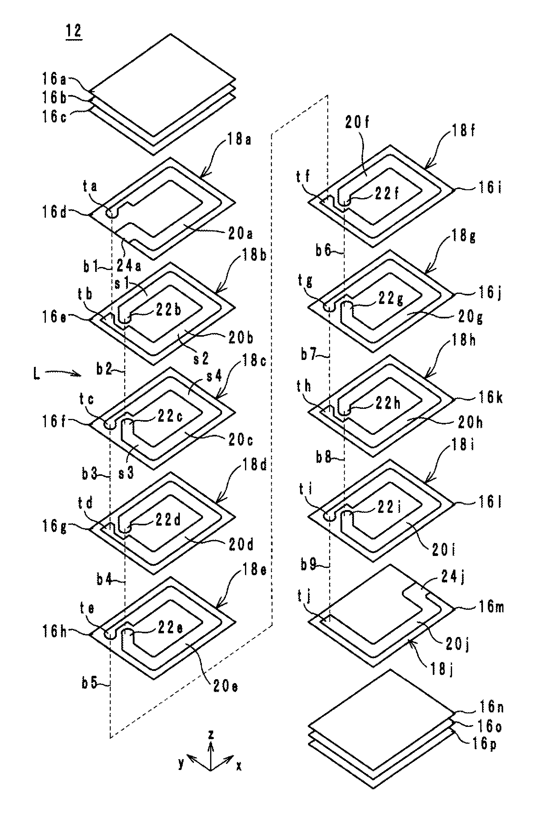
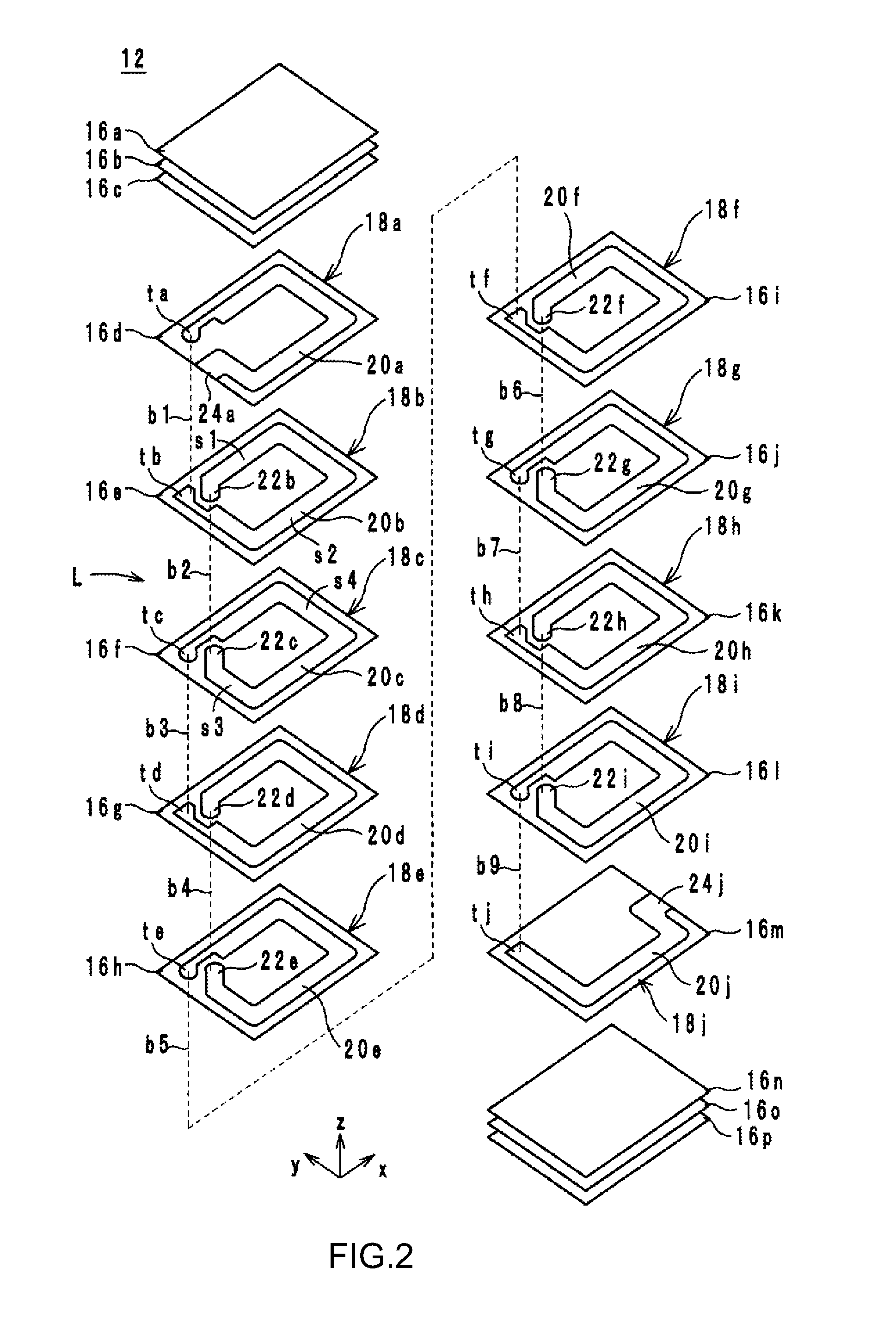
[0023]Hereafter, an electronic component 10 according to a...


PUM


Abstract

In an electronic component having a built-in coil composed of coil conductors with a length of one turn, the inductance value can be increased while suppressing generation of short circuits inside the coil conductors. The electronic component includes a multilayer body formed by stacking a plurality of magnetic layers on top of one another. The built-in coil includes coil conductors and via hole conductors. The coil conductors each have a ring-shaped coil portion having a cut out portion in one side of one corner thereof, and a connecting portion that form an obtuse angle with a side extending from one end portion of the coil portion and is positioned in a region enclosed or surrounded by the coil portion. Via hole conductors connect the plurality of coil conductors to one another.

Description

CROSS REFERENCE TO RELATED APPLICATIONS[0001]The present application is a continuation of International Application No. PCT / JP2010 / 050098, filed Jan. 7, 2010, which claims priority to Japanese Patent Application No. 2009-002159 filed Jan. 8, 2009, the entire contents of each of these applications being incorporated herein by reference in their entirety.TECHNICAL FIELD[0002]The present invention relates to electronic components, and more specifically, to electronic components having built-in coils.BACKGROUND[0003]A known multilayer electronic component is described in Japanese Unexamined Patent Application Publication No. 2006-66829 (Patent Document 1). FIGS. 8A and 8B are plan views of respective ceramic green sheets 202a and 202b used in the multilayer electronic component.[0004]In the multilayer electronic component described in Patent Document 1, the ceramic green sheet 202a illustrated in FIG. 8A and the ceramic green sheet 202b illustrated in FIG. 8B are alternately stacked. Th...

Claims


Application Information

Patent Timeline
IPC IPC(8): H01F5/00H01F27/02H01F27/28
CPCH01F17/0013H01F2017/0073H01F2017/002H01F27/292H01F17/00H01F27/28
Inventor BANNO, YOSHIKO
Owner MURATA MFG CO LTD
Why Eureka
Try Eureka