High-resolution optical detection of the three-dimensional shape of bodies

a three-dimensional shape, high-resolution technology, applied in the field of high-resolution optical detection of the three-dimensional shape of the body, can solve the problems of insufficient depth of field, insufficient to know the internal and external parameters of the camera alone, and the entire volume of the 3d digitizer is too large for many orthopedic stores

Inactive Publication Date: 2013-01-29
CORPUS E
View PDF11 Cites 12 Cited by
  • Summary
  • Abstract
  • Description
  • Claims
  • Application Information

AI Technical Summary

Benefits of technology

[0016]Thus, an evaluation of the photogrammetric marks of the surface and the marks on the body as well as of the light pattern of the at least one light projector on the marked surface and in the area of the marks on the body, the internal and external parameters of the at least one triangulation arrangement are co-determined for each image capturing position in each image capturing process. All internal and external parameters of the measuring head consisting of the camera and the light projector are thus automatically determinable using photogrammetric methods, more specifically simultaneously with the 3D measurement proper, without a separate, complicated calibration procedure using a calibration body being required. In doing so, the parameters of the camera are determined by evaluation of the photogrammetric marks and the parameters of the triangulation arrangement by evaluation of the position of the light trace on the marked surface and of the body region provided with marks in relation to the marks. Using the parameters determined in this way and using methods of photogrammetry, the 3D spatial shape of the body or body part is then determined by evaluation of the position of the light pattern on the body or body part in the images captured by the at least one camera. Since the parameters are co-determined each time, the demands on the stability of the triangulation arrangement are low and the mechanical guide and the drive may be configured to be very simple and favorably priced, since the mechanical accuracy thereof does not influence the accuracy of the photogrammetric determination of the camera position.
[0021]Since the photogrammetric self-calibration is carried out continuously along with the actual digitization of the foot, the object according to the invention of providing a very cost-efficient, self-calibrating and high-resolution 3D digitizer is thus achieved, which, except for additional photogrammetric marks on the body, applied by means of a simple elastic band, for example, manages without a photogrammetric marking of the body to be digitized.
[0022]A further advantage consists in that the photogrammetric marks of the surface and on the body (preferably on a band) may be configured purely in black and white. Owing to its high brightness, the projected light pattern or light line can be easily recognized in the image of a black-and-white camera. The method according to the invention does therefore not require a color camera, which again constitutes a considerable simplification and cost reduction.
[0024]Furthermore, it is also known to configure a triangulation measuring head in such a way that one light pattern projector each is arranged on ether side of a single camera; in particular concave spatial shapes can be better detected thereby.
[0027]The method and the arrangement according to the invention therefore permit the construction of very cost-efficient and yet precise and high-resolution self-calibrating 3D digitizers in comparison with the prior art.

Problems solved by technology

But it is awkward in the case of a simple and easily accessible digitizer to arrange further marked surfaces in the background of the upper image field.
The depth of field would not be sufficient and the entire volume of the 3D digitizer would be too large for many orthopedic stores.
In order to obtain a calibration-free or self-calibrating 3D digitizer, which preferably operates according to the light section procedure, it is not sufficient to know the internal and external parameters of the camera alone.

Method used


Image

  • High-resolution optical detection of the three-dimensional shape of bodies
  • High-resolution optical detection of the three-dimensional shape of bodies
  • High-resolution optical detection of the three-dimensional shape of bodies

Examples


Embodiment Construction

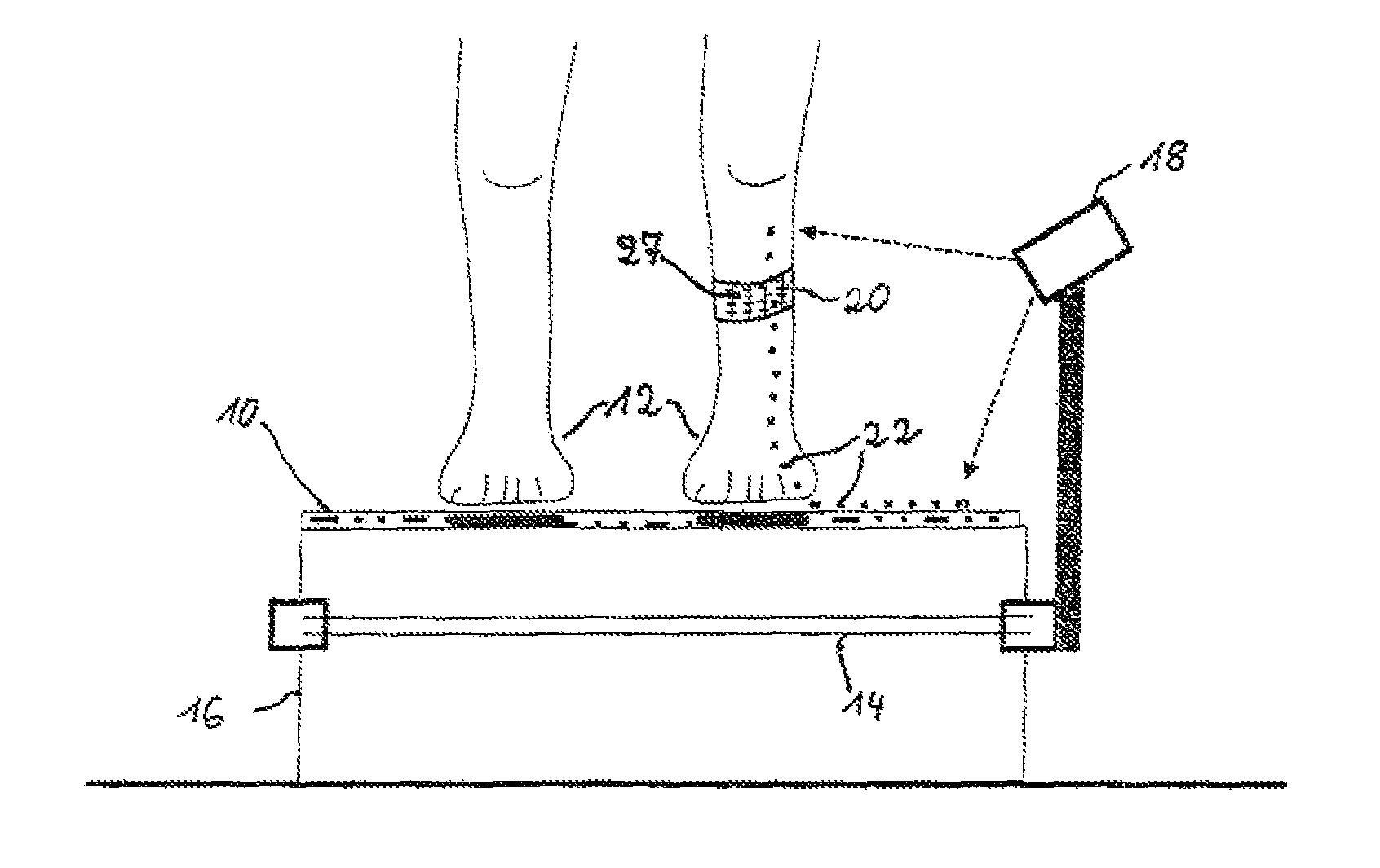
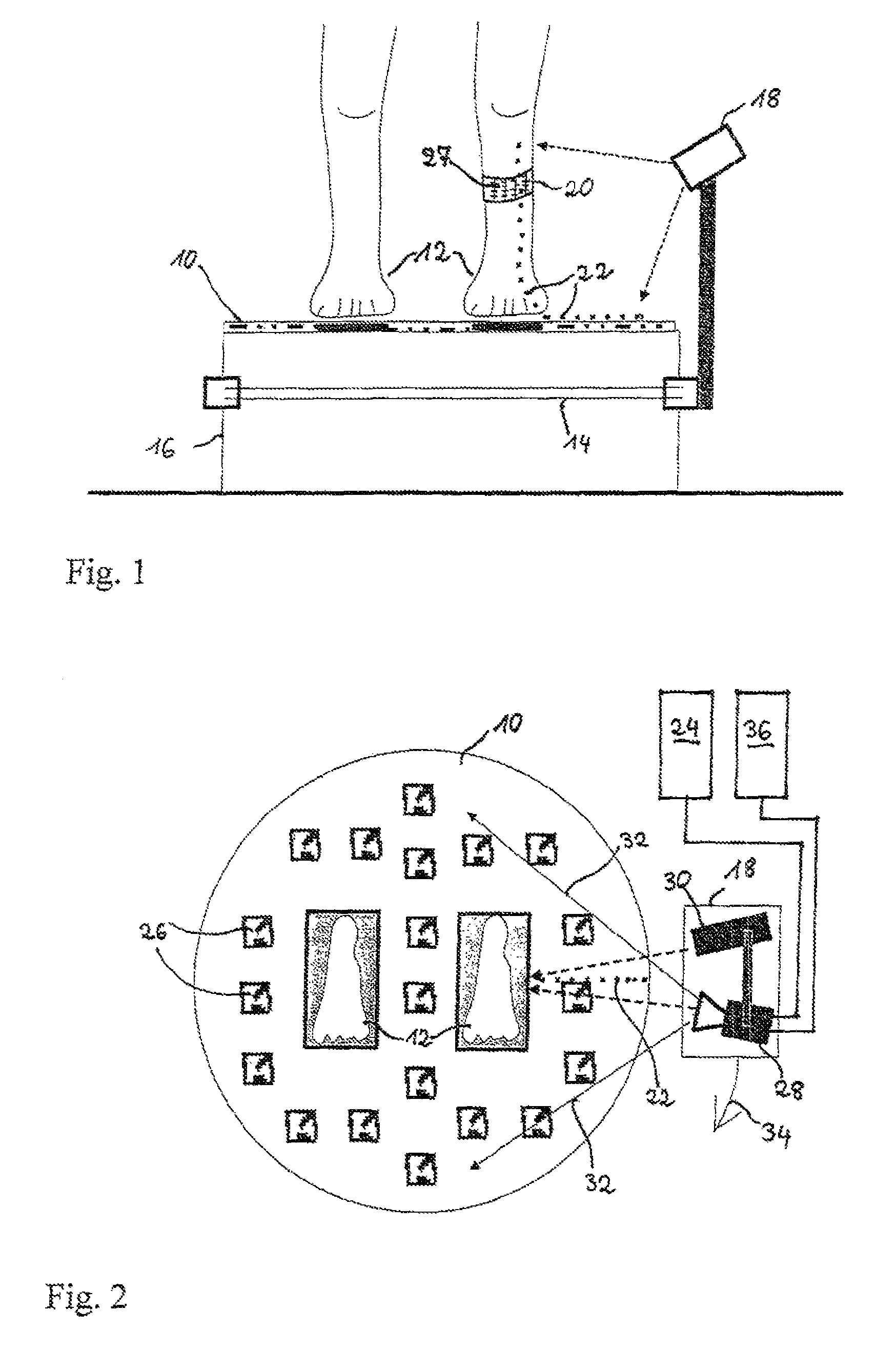
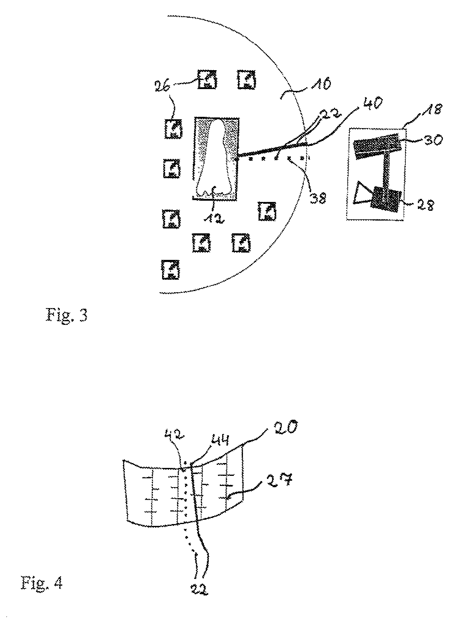
[0033]The exemplary embodiment selected describes the 3D digitization of a foot, for example for the production of an adapted orthopedic shoe. FIG. 1 shows a side view of a photogrammetrically marked surface 10 on which a patient stands, with his feet 12 being visible. A triangulation arrangement 18 with a camera and a light line projector can be mechanically moved around the patient along a substantially circular guide 14 which is mounted to a support 16. Instead of a light line projector, use may also be made of a projector that projects a more complicated light pattern. The mechanical arrangement may be of a simple design; a manual movement of the triangulation arrangement without a guide is also possible. A narrow, preferably elastic, photogrammetrically marked band 20 is in tight fitting contact with a leg above the foot to be digitized; it will be understood that a respective band can also be fitted to each foot, or some other form of applying the marks may be selected as well...


PUM


Abstract

In a cost-efficient method and arrangement for 3D digitization of bodies and body parts, which produces dense and exact spatial coordinates despite imprecise optics and mechanics, the body to be digitized is placed on a photogrammetrically marked surface, a photogrammetrically marked band is fitted to the body or body part to be digitized, and a triangulation arrangement comprised of a camera and a light pattern projector is moved on a path around the body. By a photogrammetric evaluation of the photogrammetric marks of the surface and the band situated in the image field of the camera, and of the light traces of the light projector on the marked surface and the marked band, all unknown internal and external parameters of the triangulation arrangement are determined, and the absolute spatial coordinates of the body or body part are established from the light traces on the non-marked body with high point density and high precision without any separate calibration methods.

Description

FIELD OF THE INVENTION[0001]The invention relates to a method for precise optical detection of the 3D spatial shape of bodies and body parts, and to an arrangement for implementing such method.BACKGROUND OF THE INVENTION[0002]The detection of the three-dimensional spatial shape of bodies or body parts, in particular of human body parts, such as legs, torso or feet, is an important aspect in the production or assignment of fitting articles of clothing, orthopedic aids such as compression stockings, prostheses and ortheses and also in the production or assignment of fitting shoes. Numerous optical 3D scanners are on the market, most of which operate either on the basis of the methods of laser triangulation (see, e.g., PEDUS foot scanner of the company of Vitronic Dr. Stein, www.vitus.de) or stripe projection (see, e.g., bodyScan of the Breuckmann company, www.breuckmann.com). Both methods are based on triangulation, i.e. a stable spatial triangular arrangement of a light projector, a ...

Claims


Application Information

Patent Timeline
Patent Type & Authority Patents(United States)
IPC IPC(8): G06K9/00
CPCA61B5/0064A61B5/1074A61B5/1077A61B5/1127
Inventor RUTSCHMANN, DIRKPFEIFFER, RENE
Owner CORPUS E
Why Eureka
Try Eureka