Centrifugal dryer

a centrifugal dryer and centrifugal technology, applied in centrifuges, separation processes, lighting and heating apparatus, etc., can solve the problems of seam and connection points, particularly prone to sealing problems, and the seam and connection points are easily sealed, so as to avoid turbulence, facilitate assembly and disassembly of the screen members, and facilitate releasability

Active Publication Date: 2013-02-05
GALA INDUSTRIES INC
View PDF18 Cites 11 Cited by
  • Summary
  • Abstract
  • Description
  • Claims
  • Application Information

AI Technical Summary

Benefits of technology

[0025]In accordance with a preferred embodiment of the invention, the clamping rail can in this respect be releasably hung at the connection body by means of hinge joint bolts so that the clamping rail is, on the one hand, easily releasably from the connection body by axially pulling the hinge joint bolt and / or pulling off the clamping rail itself and, on the other hand, can hinge about a hinge joint axis parallel to the longitudinal axis of the screen with respect to the connection body, whereby the screen member pushed under or over the clamping rail can be clamped by clamping the tension belts hinged thereto. In a further development of the invention, said clamping rail can form together with a marginal web of the connection piece a slit-shaped reception part into which the screen member can be inserted at the rim side. If the tension belts hinged at the clamping rail are tightened, the mouth closes, so-to-say, and the clamping rail is pulled onto the marginal web of the connection piece, whereby the screen member is securely fixed.
[0026]To achieve a simple and fast assembly and disassembly of the screen members, a respective clamping means which can be actuated without a tool and which allows the tension belts to be relaxed by hand is advantageously associated with the tension belts. A fast-clamping lever in the manner of a ski-boot buckle can in this respect be provided for each tension belt and is fastenable to an end of the respective tension belt and is able to be pivoted at the oppositely disposed end of the tension belt, in particular is able to be hung in by means of a hanger. Instead of such a shape-matched hanger, optionally, in particular with pliable tension belts, provision can be made that the oppositely disposed end of the tension belt is looped through a fixing member attached to the clamping lever or is wrapped around it so that the tension belt is held by clamping and is clamped by switching the clamping lever.
[0027]The screen design can particularly advantageously consist of screen members mutually overlapping in the peripheral direction for rotationally standing screens in which the initially named rotor is rotationally received. Whereas with rotary screens which rotate themselves and optionally rotate at high speeds in a liquid bath, as is shown in DE 14 32 766, and the screen, considered in the peripheral direction, was made up of only a single screen member and screen overlap regions by flush joining together as butt joints by means of suitable frame sections were preferred to avoid turbulences induced by the overlap regions, in contrast to this such overlap edges do not play any role with standing screens. It is rather the case that particularly with standing screens the variable connection possibilities for connection shafts and the like on the peripheral side are of advantage since particularly standing screens have such connection parts at the peripheral side.

Problems solved by technology

Depending on the pellet size, sealing problems occur at the screens in this process.
The corresponding seam and connection points are in this respect particularly prone to sealing problems.
On the one hand, they are relatively complex and / or expensive to manufacture since care must be taken that the screen members themselves are not deformed on the welding tight of the holding members at the screen member rims.
If nevertheless welding deformation occurs, sealing problems arise.
On the other hand, the screen members can only be rolled forward with difficulty, in particular when very stiff screen members have to be used for corresponding applications.
The assembly and disassembly of the screen members is hereby made correspondingly more difficult.

Method used


Image

  • Centrifugal dryer
  • Centrifugal dryer
  • Centrifugal dryer

Examples


Embodiment Construction

[0034]Further scope of applicability of the present invention will become apparent from the detailed description given hereinafter. However, it should be understood that the detailed description and specific examples, while indicating preferred embodiments of the invention, are given by way of illustration only, since various changes and modifications within the spirit and scope of the invention will become apparent to those skilled in the art from this detailed description.

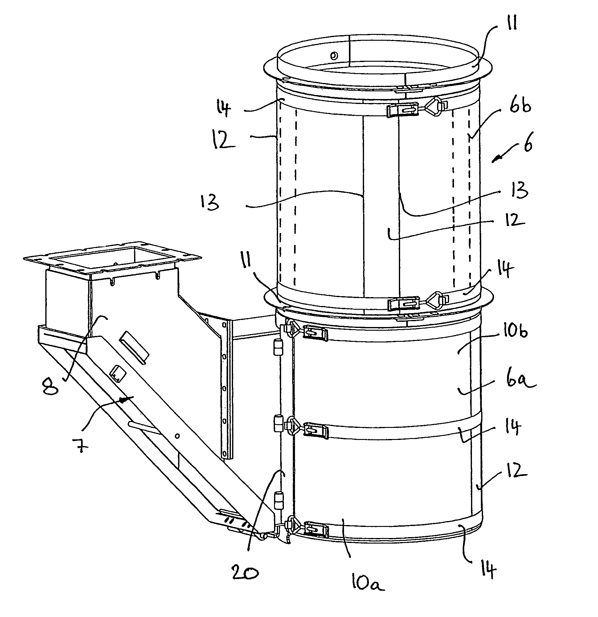
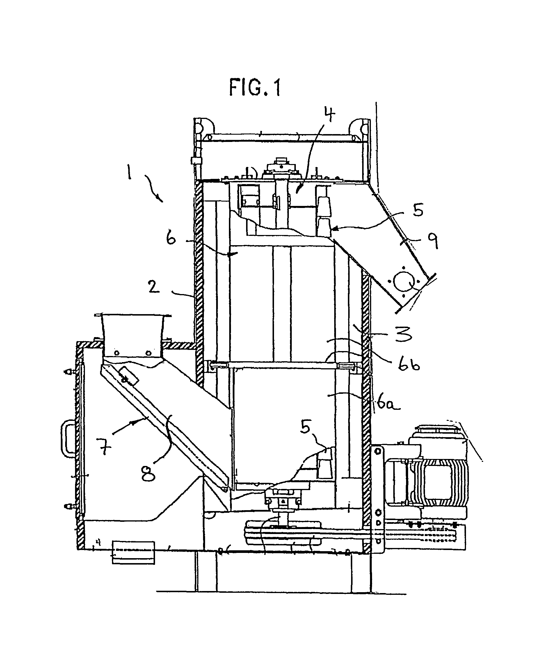
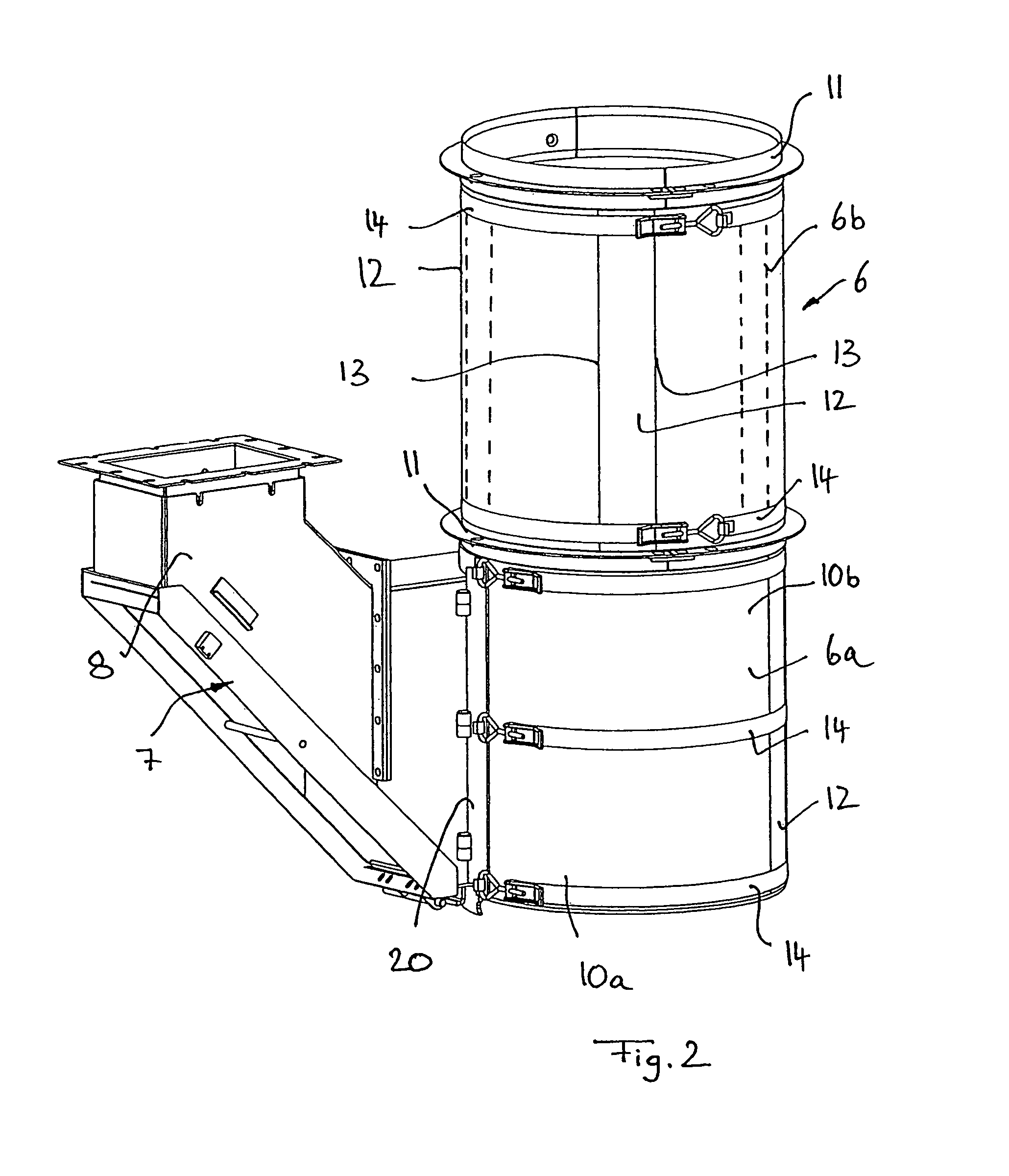
[0035]The centrifugal dryer 1 drawn in FIG. 1 includes a housing 2 which is—roughly speaking—cylindrical overall and which is closed by a door which is provided at the jacket-surface side and through which the inner space 3 of the housing 2 is accessible. A rotor 4 is arranged in the inner space 3 of the housing 2 and can be driven by an upright rotary axle by means of a drive motor not shown in detail. As FIG. 1 indicates, the rotor 4 includes a plurality of bucket-like conveying members 5 which are arranged pro...


PUM

PropertyMeasurementUnit
tensionaaaaaaaaaa
sizeaaaaaaaaaa
flexibleaaaaaaaaaa

Abstract

A centrifugal dryer for the separation of pellet-like substances from process water including a housing, a rotor arranged in the housing and a screen surrounding the rotor at the peripheral side. The screen has at least one porous screen member which is placed in an arcuate manner around at least one screen carrier hoop and is releasably fastened thereto. The screen is composed of a plurality of screen members which mutually overlap in the peripheral direction and are clamped tight to the screen carrier hoop by one or more tension belts which wrap around the mutually overlapping screen members at the peripheral side.

Description

[0001]This is a national stage of PCT / EP08 / 002168 filed Mar. 18, 2008 and published in German, which has a priority of German no. 20 2007 003 978.6 filed Mar. 19, 2007 and German no. 20 2007 004 462.3 filed Mar. 27, 2007, hereby incorporated by reference.BACKGROUND OF THE INVENTION[0002]1. Field of the Invention[0003]The present invention relates to a centrifugal dryer for the separation of pellet-like substances from process water, comprising a housing, a rotor arranged in the housing and a screen surrounding the rotor at the peripheral side, with the screen having at least one porous screen member which is placed in an arcuate manner around at least one screen carrier hoop and is releasably fastened thereto.[0004]2. Description of the Related Art[0005]Plastic pellets which are manufactured by underwater pelletizing are continuously separated from the process water of the pelletizer system by centrifugal dryers connected downstream of the underwater pelletizers. Such centrifugal dr...

Claims


Application Information

Patent Timeline
Patent Type & Authority Patents(United States)
IPC IPC(8): F26B17/24F26B11/12B01D35/00
CPCF26B17/24F26B5/08B04B5/12B04B7/16
Inventor VELTEL, JUERGENBAASKE, THOMASPETERS, MARKUSMAESMANNS, CHRISTOPH
Owner GALA INDUSTRIES INC
Why Eureka
Try Eureka