Emitter for ionic thruster

a technology of ion thruster and emitter, which is applied in the direction of discharge tube main electrodes, ion beam tubes, machines/engines, etc., can solve the problems of emitter not working satisfactorily, emitter has met with production difficulties, and is difficult to make flat emitters

Active Publication Date: 2013-02-05
SN DETUDE & DE CONSTR DE MOTEURS DAVIATION S N E C M A
View PDF8 Cites 0 Cited by
  • Summary
  • Abstract
  • Description
  • Claims
  • Application Information

AI Technical Summary

Benefits of technology

[0023]It is an object of the invention to solve the above problems, and in particular to make it possible to build ion thrusters with a thrust greater than 1 mN, typically of around 5 to 10 mN, in a simplified and reliable process ensuring highly accurate construction.
[0029]Making an emitter with a circular slit automatically protects against edge effects (high currents at the ends).
[0030]The particular structure recommended for the circular-slitted emitter enables the accurate construction of a circular slit measuring for example 1.5 micrometers across a diameter of 30 to 100 mm owing to the geometry which allows self-centering and ensures the possibility of adjustment, in such a way as to achieve an accuracy that could not be obtained by simple machining.

Problems solved by technology

It is however very difficult to make flat emitters, such as that shown in FIGS. 2-4, with a slit length of more than 70 mm that are straight and planar to within 1 micrometer, and with a surface finish of 0.05 μm rms or better.
Linear emitter technology has no difficulty producing thrusts of less than 1 mN, but becomes more difficult at higher thrusts, of around 5 to 10 mN for example.
So far, however, this type of emitter has met with production difficulties and has not worked satisfactorily.

Method used


Image

  • Emitter for ionic thruster
  • Emitter for ionic thruster
  • Emitter for ionic thruster

Examples


Embodiment Construction

[0040]FIGS. 5 and 6 show the general structure of an example of a circular emitter 100 according to the invention, and FIG. 7 shows how such a circular emitter 100 is incorporated in an ion thruster.

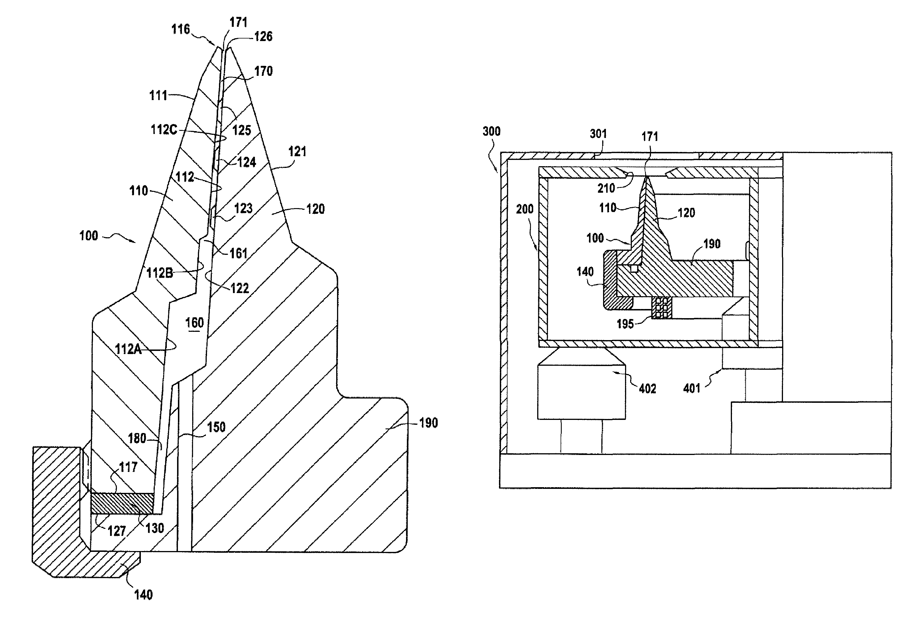
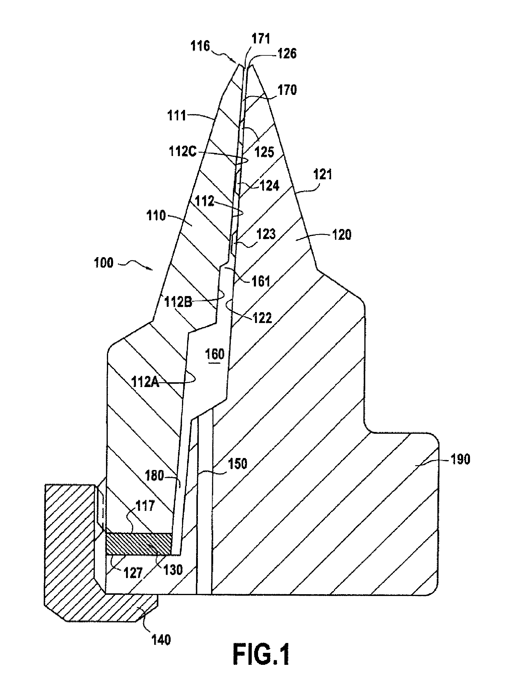
[0041]The emitter 100 comprises an internal part 120 having symmetry of revolution about an axis O, with a base 190 and a projecting portion whose external face 122 (FIG. 1) acts in conjunction with the internal face 112 of an external part 110 which also has symmetry of revolution about the axis O, is fitted onto the internal part 120, and is held against this internal part 120 by connecting means such as a nut 140.

[0042]An internal reservoir and a circular slit, neither of which is shown in FIGS. 5-7, are defined between the internal and external parts 120 and 110, as will be explained below with reference to FIG. 1.

[0043]FIG. 7 shows how the circular emitter 100 is incorporated in an ion thruster such as a field-emission or colloid thruster.

[0044]The emitter 100 is mounted close to an...


PUM


Abstract

An emitter for an ion thruster. The emitter is a field-effect emitter for a field emission electric propulsion or colloid thruster. The field-effect emitter has a first and second portions defining an internal reservoir for supplying a liquid metal or a conducting ionic liquid and has a slit connecting the internal reservoir to an exit orifice.

Description

FIELD OF THE INVENTION[0001]This invention relates to an emitter for an ion thruster.[0002]More specifically, the invention relates to a field-effect emitter for a field emission electric propulsion or colloid thruster, comprising a first portion and a second portion defining an internal reservoir for supplying a liquid metal or a conducting ionic liquid, and a slit connecting the internal reservoir to an exit orifice.PRIOR ART[0003]Field emission electric propulsion (FEEP) thrusters have been known since the 1970s.[0004]These thrusters are supplied either with liquid cesium (which has a melting point of 28.5° C.), or liquid indium.[0005]More recently, it has been proposed that novel electrically conducting liquids be used for colloid thrusters employing a geometry similar to that of FEEP thrusters.[0006]Examples of ion thrusters are described in the following publication: “Field emission electric propulsion development status”, C. Bartoli and D. Valentian, 17th IEPC Tokyo, May 1984...

Claims


Application Information

Patent Timeline
Patent Type & Authority Patents(United States)
IPC IPC(8): F03H1/00
CPCF03H1/005H01J27/26
Inventor VALENTIAN, DOMINIQUE
Owner SN DETUDE & DE CONSTR DE MOTEURS DAVIATION S N E C M A
Why Eureka
Try Eureka