Piston head assembly for radio controlled cars shock absorber and method

a technology of shock absorber and piston head, which is applied in the field of piston head assembly of radio controlled cars, can solve the problems of complex devices that do provide performance improvement, prone to being less robust than desirable, and inconsistent devices, and achieve the effect of improving the speed of the ra

Active Publication Date: 2018-08-07
ANKNEY MICHAEL A
View PDF16 Cites 1 Cited by
  • Summary
  • Abstract
  • Description
  • Claims
  • Application Information

AI Technical Summary

Benefits of technology

[0018]An object of the present invention is to provide an improved R / C shock absorber that improves racing lap times.
[0019]Another possible object of the present invention is to provide an improved piston head assembly for R / C shock absorbers that improves racing performance.
[0021]Yet another possible object of the present invention is to provide a reliable and simplified piston for R / C shock absorbers which provides for a quick rebound damping force to reliably improve lap times.
[0022]A further possible object of the present invention is to provide an improved piston head assembly for R / C absorbers without unintended consequences to drivability.
[0033]Another step may include providing the at least first and second valve members are also sufficiently resilient to engage and close the first and second one-way valves when the piston head is not moving in the piston cylinder.

Problems solved by technology

Devices that do provide performance improvements are often complex and inconsistent or prone to being less robust than desirable.
When a vehicle encounters a bump or uneven terrain, the suspension compresses during the compression stroke.
In the R / C car setting, shock absorbers provide a similar function but on a much smaller scale, which leads to unique problems specific to the R / C car application, including product materials, size difficulties, and the like.

Method used


Image

  • Piston head assembly for radio controlled cars shock absorber and method
  • Piston head assembly for radio controlled cars shock absorber and method
  • Piston head assembly for radio controlled cars shock absorber and method

Examples


Embodiment Construction

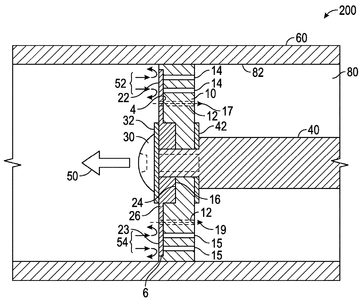
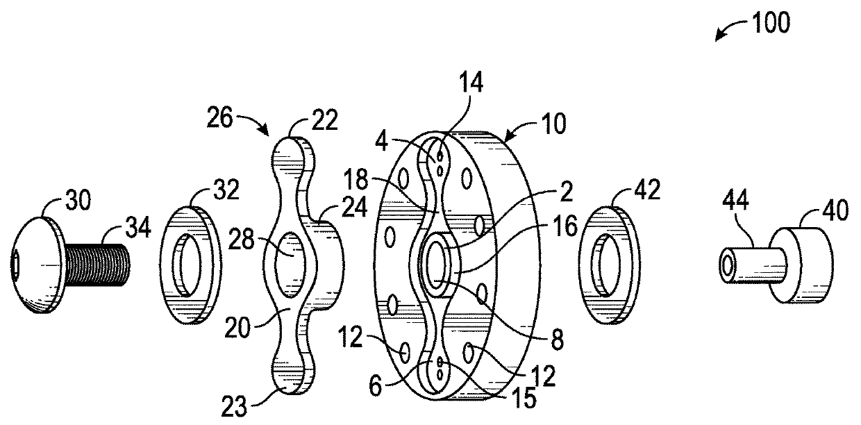
[0046]Turning now to the drawings, and more particularly FIG. 1, there is depicted an exploded perspective view of piston head assembly 100 for an R / C shock absorber in accord with one possible non-limiting embodiment of the present invention. Generally speaking, piston head assembly 100 comprises sealing member 26 positioned on one side of piston head 10, with both sealing member 26 and piston head 10 attached to piston rod 40 by fastener 30. In this non-limiting embodiment, sealing member 26 is mounted on a side of piston head 10 opposite to piston rod 40. Bolt stem 34 is inserted through washer 32, sealing member hole 28, central aperture 8, and washer 42 before connecting with piston rod connection 44. Fastener 30 may comprise various fasteners suitable for connecting with rod 40, including, but not limited to screws, nuts, and the like. In this embodiment, washers 32 and 42 are placed between fastener 30 and sealing member 26, and piston head 10 and piston rod 40, respectively....


PUM


Abstract

An apparatus and method for a piston head assembly for an R / C car shock absorber provides for differing flow rates through the piston depending on whether the piston is presently in rebound or compression movement. A piston head may be constructed with a plurality of separate recesses further having at least first and second one way valve holes and a plurality of two way valve holes surrounding the central recess. In one embodiment, two sealing members fit within two separate recesses whereby the sealing member keeps the first and second one way valve holes generally closed. When fluid flow contacts the sealing member during the rebound stroke, fluid flows through the first and second one way valve holes moves the seal member to the open position thereby providing more fluid flow and a quicker rebound damping response.

Description

BACKGROUND OF THE INVENTIONField of the Invention[0001]The present invention relates generally to shock absorbers and, more particularly in some non-limiting embodiments, to a piston head assembly for an R / C (Radio controlled) car shock absorber.Background of the Invention[0002]The sport of R / C vehicle racing is highly competitive. Professional drivers of R / C vehicles who race at the upper levels of the sport are well paid by sponsors. Engineers and hobbyists have worked for decades to constantly improve performance of R / C vehicles in every aspect of operation including motors, tires, weight, construction, shock absorbers, and the like. R / C vehicle enthusiasts are constantly searching for improved performance. Even small changes that can improve performance of lap speed by fractions of seconds are highly desirable and sought after. However, given the long term intense competition and efforts for improvements in this field, it is somewhat unusual to find improvements that reliably im...

Claims


Application Information

Patent Timeline
Patent Type & Authority Patents(United States)
IPC IPC(8): F16F9/32F16F9/36
CPCF16F9/3214F16F9/368F16F9/3271B60Y2200/81B60G13/08B60G17/08F16F9/348F16F9/3481F16F9/512F16F9/516B60G2202/24B60G2206/41B60G2300/20B60G2500/112B60G2600/21
Inventor ANKNEY, MICHAEL A
Owner ANKNEY MICHAEL A
Why Eureka
Try Eureka