Liquid crystal composition and liquid crystal display device

a liquid crystal composition and display device technology, applied in liquid crystal compositions, thin material processing, chemistry apparatus and processes, etc., can solve the problems of large contrast ratio of devices, small electric power consumption, low threshold, etc., and achieve the effect of increasing dielectric anisotropy, increasing maximum temperature, and increasing dielectric anisotropy

Active Publication Date: 2013-02-05
JNC CORP +1
View PDF14 Cites 8 Cited by
  • Summary
  • Abstract
  • Description
  • Claims
  • Application Information

AI Technical Summary

Benefits of technology

[0062]Second, main characteristics of the component compounds and main effects of the compounds on the characteristics of the composition will be explained. The main characteristics of the component compounds are summarized in Table 2 on the basis of the effects of the invention. In Table 2, the symbol L stands for “large” or “high”, the symbol M stands for “medium”, and the symbol S stands for “small” or “low.” The symbols L, M and S are classified according to a qualitative comparison among the component compounds, and 0 (zero) means that “a value is nearly zero.”
[0064]Main effects of the component compounds on the characteristics of the composition upon mixing the component compounds with the composition are as follows. The compound (1) significantly increases the dielectric anisotropy. The compound (2) increases the maximum temperature, and increases the dielectric anisotropy. The compound (3) decreases the minimum temperature, and decreases the viscosity. The compound (4) decreases the minimum temperature and increases the dielectric anisotropy. The compound (5) increases the dielectric anisotropy.
[0065]Third, a combination of the components in the composition, desirable ratios of the component compounds and the basis thereof will be explained. A combination of the components in the composition is the first and second components, the first, second and third components, the first, second and fourth components, the first, second and fifth components, the first, second, third and fourth components, the first, second, third and fifth components, the first, second, fourth and fifth components, and the first, second, third, fourth and fifth components. A desirable combination of the components in the composition is the first, second, third and fourth components and the first, second, third, fourth and fifth components.
[0066]A desirable ratio of the first component is approximately 5% by weight or more for increasing the dielectric anisotropy, and approximately 50% by weight or less for decreasing the minimum temperature. A more desirable ratio is in the range of approximately 7% by weight to approximately 35% by weight. An especially desirable ratio is in the range of approximately 10% by weight to approximately 20% by weight.
[0067]A desirable ratio of the second component is approximately 5% by weight or more for increasing the dielectric anisotropy, and approximately 50% by weight or less for decreasing the minimum temperature. A more desirable ratio is in the range of approximately 5% by weight to approximately 35% by weight. An especially desirable ratio is in the range of approximately 5% by weight to approximately 20% by weight.
[0068]A desirable ratio of the third component is approximately 30% by weight or more for decreasing the viscosity, and approximately 75% by weight or less for increasing the dielectric anisotropy. A more desirable ratio is in the range of approximately 40% by weight to approximately 70% by weight. An especially desirable ratio is in the range of approximately 50% by weight to approximately 65% by weight.

Problems solved by technology

A large dielectric anisotropy of the composition contributes to a low threshold voltage, small electric power consumption and a large contrast ratio of the device.
In the case where the stability is high, the device has a long service life.
A large elastic constant of the composition contributes to a large contrast ratio and a short response time of the device.

Method used


Image

  • Liquid crystal composition and liquid crystal display device
  • Liquid crystal composition and liquid crystal display device
  • Liquid crystal composition and liquid crystal display device

Examples


example 1

[0133]

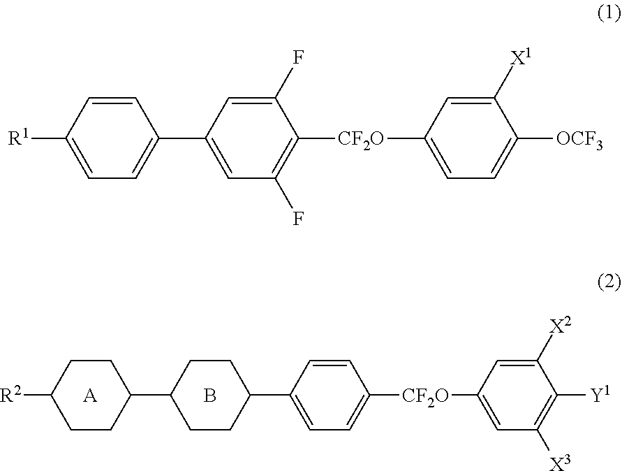
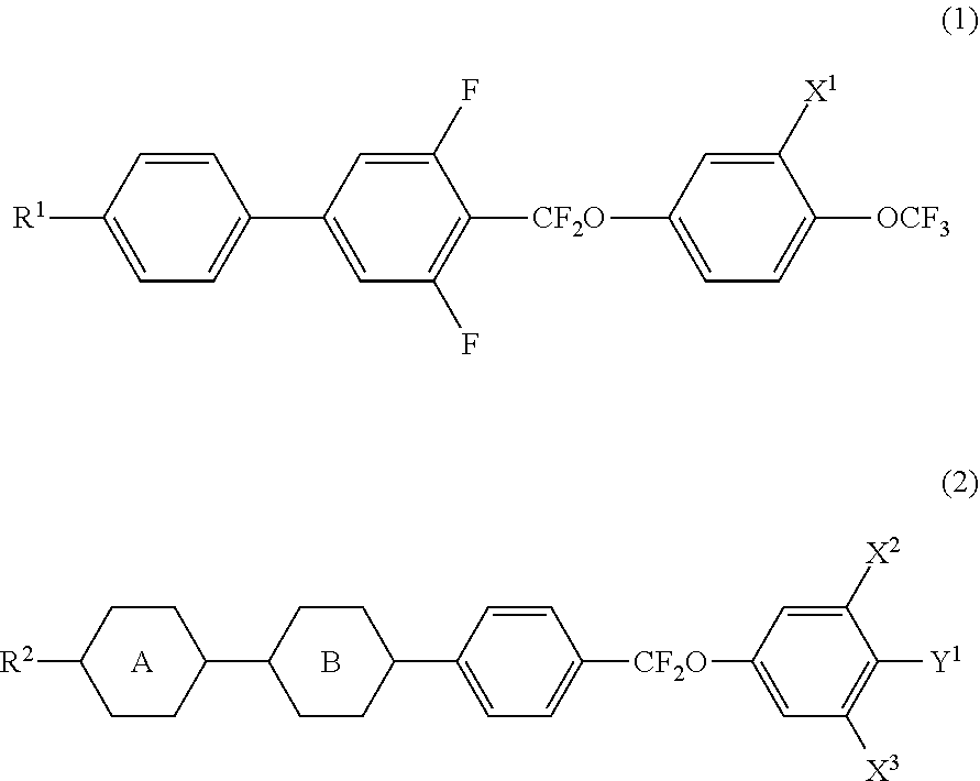
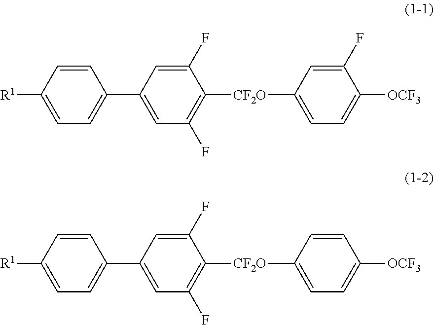
3-BB(F,F)XB(F)—OCF3(1-1-1)6%3-HBBXB(F,F)—F(2-1-1)7%5-HBBXB(F,F)—F(2-1-1)8%V—HH-3(3-1-1)40% V—HHB-1(3-5-1)5%1-BB(F)B-2V(3-7-1)5%2-BB(F)B-2V(3-7-1)3%3-HHXB(F,F)—F(4-6-1)8%3-HBB(F,F)—F(4-12-1)10% 3-BB(F,F)XB(F,F)—F(4-14-1)8%

[0134]NI=78.6° C.; Tc≦−20° C.; Δn=0.107; Δ∈=5.8; Vth=1.87 V; η=9.8 mPa·s; VHR-1=99.2%; VHR-2=98.2%; VHR-3=98.1%.

example 2

[0135]

3-BB(F,F)XB(F)—OCF3(1-1-1)7%3-HBBXB(F,F)—F(2-1-1)8%3-HH-4(3-1-1)30% 3-HH-5(3-1-1) 10% 3-HB—O2(3-2-1)9%3-HHB-1(3-5-1)4%3-HHB—O1(3-5-1)4%5-HBB(F)B-2(3-13-1)4%5-HB—CL(4-1-1)8%2-HHB—CL(4-4-1)3%3-HHB—CL(4-4-1)3%3-BB(F)B(F,F)—F(4-13-1)4%3-HHB(F)B(F,F)—F(4-17-1)3%4-BB(F)B(F,F)XB(F,F)—F(5-1-1)3%

[0136]NI=88.8° C.; Tc≦−30° C.; Δn=0.098; Δ∈=3.7; Vth=2.10 V; η=10.4 mPa·s; VHR-1=99.0%; VHR-2=98.3%; VHR-3=98.0%.

example 3

[0137]

3-BB(F,F)XB(F)—OCF3(1-1-1)4%4-BB(F,F)XB(F)—OCF3(1-1-1)4%5-BB(F,F)XB(F)—OCF3(1-1-1)4%3-HBBXB(F,F)—F(2-1-1)5%3-HHBXB(F,F)—F(2-2-1)5%V—HH-3(3-1-1)30% 1V—HH-4(3-1-1)8%4-HHEH-3(3-4-1)5%4-HHEH-5(3-4-1)5%3-HB(F)HH-5(3-9-1)3%3-HB—CL(4-1-1)5%1V2-BB—F(4-2-1)4%1V2-BB—CL(4-3-1)4%3-HHXB(F,F)—F(4-6-1)4%3-HHEB(F,F)—F(4-7-1)3%3-HBEB(F,F)—F(4-10-1)3%3-BB(F,F)XB(F,F)—F(4-14-1)4%

[0138]NI=72.4° C.; Tc≦−20° C.; Δn=0.086; Δ∈=4.5; Vth=1.97 V; η=9.4 mPa·s; VHR-1=99.1%; VHR-2=98.2%; VHR-3=97.9%.


PUM

PropertyMeasurementUnit
temperatureaaaaaaaaaa
frequencyaaaaaaaaaa

Abstract

A liquid crystal composition that satisfies at least one characteristic, such as, high maximum temperature of a nematic phase, low minimum temperature of a nematic phase, small viscosity, suitable optical anisotropy, large dielectric anisotropy, large specific resistance, large elastic constant, high stability to ultraviolet light and high stability to heat, or that is suitably balanced between at least two of the characteristics; and provides an AM device that has short response time, large voltage holding ratio, large contrast ratio, long service life and so forth. A liquid crystal composition is provided that has a nematic phase and includes a specific three-ring compound having a large dielectric anisotropy as a first component, a specific four-ring compound having a high maximum temperature and a large dielectric anisotropy as a second component, and a liquid crystal display device containing the composition.

Description

[0001]This is a Non-Provisional application, which claims priority to Japanese Patent Application No. 2010-272716, filed on Dec. 7, 2010, the contents of which are all herein incorporated by this reference in their entireties. All publications, patents, patent applications, databases and other references cited in this application, all related applications referenced herein, and all references cited therein, are incorporated by reference in their entirety as if restated here in full and as if each individual publication, patent, patent application, database or other reference were specifically and individually indicated to be incorporated by reference.BACKGROUND OF THE INVENTION[0002]1. Field of the Invention[0003]The invention relates mainly to a liquid crystal composition suitable for use in an AM (active matrix) device and so forth, and an AM device and so forth that contain the composition. More specifically, the invention relates to a liquid crystal composition having positive d...

Claims


Application Information

Patent Timeline
Patent Type & Authority Patents(United States)
IPC IPC(8): C09K19/12C09K19/34C09K19/20C09K19/30
CPCC09K19/20C09K19/3066C09K19/44Y10T428/10C09K2019/0466C09K2019/124C09K2019/0444C09K2323/00
Inventor YANAI, TAKAYOSHIHATTORI, NORIKATSU
Owner JNC CORP
Why Eureka
Try Eureka