Filter for light receiving element, and light receiving device

a technology of light receiving element and filter, applied in the direction of instruments, lenses, sensing by electromagnetic radiation, etc., can solve the problems of insufficient removal of ambient light by conventional methods, significant influence of distance measurement and object detection accuracy,

Active Publication Date: 2013-02-05
NALUX CO LTD
View PDF16 Cites 0 Cited by
  • Summary
  • Abstract
  • Description
  • Claims
  • Application Information

AI Technical Summary

Benefits of technology

[0009]The filter for a light receiving element according to the aspect of the present invention is configured in such a way that N1 / (N2)2 is minimized under constraints. As a result, the S / N ratio of the light receiving element can be maximized under the constraints.
[0023]In the present embodiment, N1 / (N2)2 can be obtained with a high accuracy when the spectral distribution of the ambient light is known. Accordingly, the light receiving device in which the S / N ratio is maximized can be produced without fail.

Problems solved by technology

When such an image pick-up device, such a distance measuring device, such an object detecting device and the like are used outdoors, in particular, accuracy of distance measurement and object detection will be significantly affected by ambient light such as the sunlight.
However, when intensity of the sunlight has a very strong influence outdoors, ambient light cannot be sufficiently removed by conventional methods.

Method used


Image

  • Filter for light receiving element, and light receiving device
  • Filter for light receiving element, and light receiving device
  • Filter for light receiving element, and light receiving device

Examples


Embodiment Construction

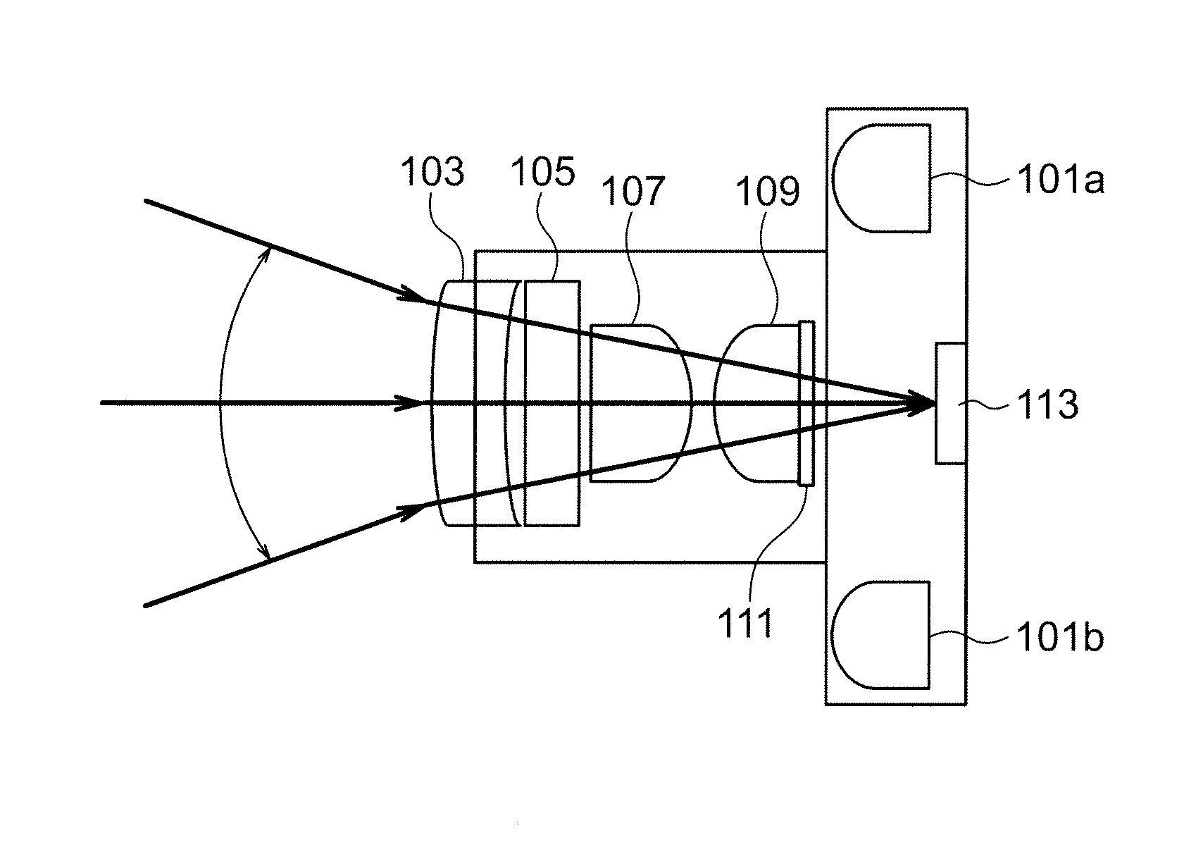
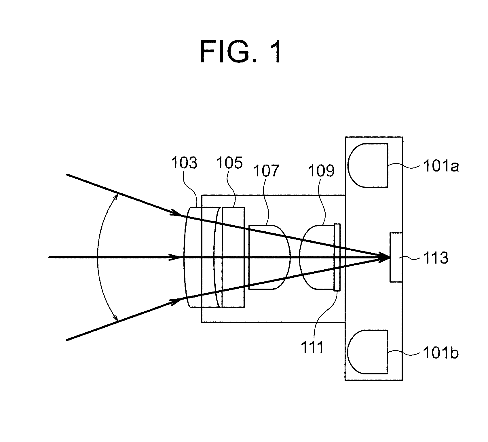
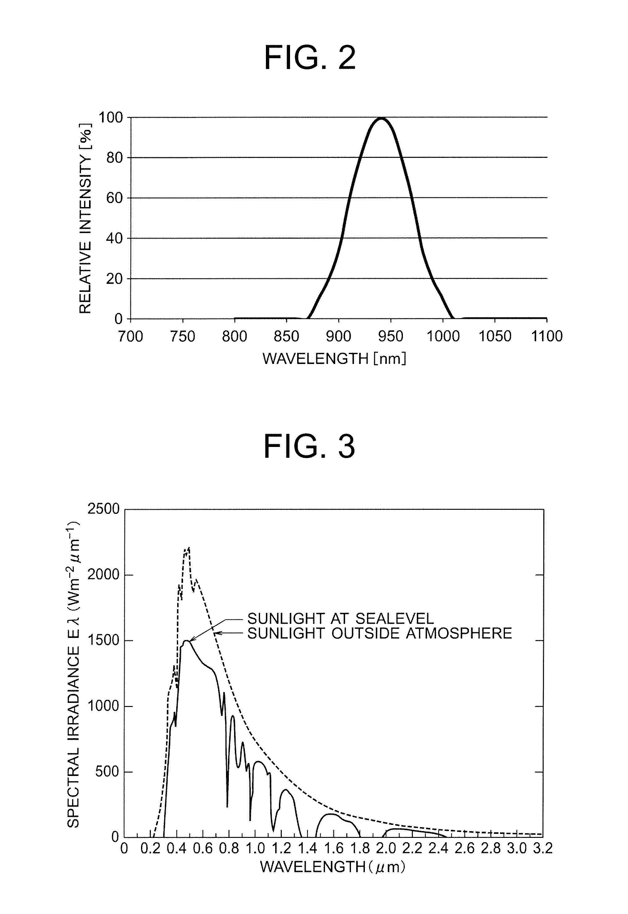
[0037]FIG. 1 shows an example of a block diagram of a distance measuring device with a filter for a light receiving element according to the present invention. In FIG. 1, light beams are emitted toward an object from a light source 101a and a light source 101b. The light sources may be lasers or light emitting diodes which emit light in the wavelength range of infrared light. The reasons why signal lights in the wavelength range of infrared light are used are that they can be used in safe because they are imperceptible to the human eye and that disturbance due to the sunlight can be reduced because radiation illuminance of the sunlight in the wavelength range of infrared light is smaller than that in the wavelength range of visible light as shown in FIG. 3. Light beams reflected by the object pass through a first lens 103, an absorbing filter 105, a second lens 107, a third lens 109 and a band-pass filter 111 and reach a light receiving element 113.

[0038]The first lens 103 may be a ...


PUM


Abstract

A filter for a light receiving element, which can sufficiently eliminate disturbance due to sunlight and the like out of doors. The filter for a light receiving element according to one embodiment of the present invention is used for a light receiving element which receives signal light having a known spectral distribution. The filter for a light receiving element according to one embodiment of the present invention is configured so that when the energy density of the ambient light in the light receiving element is represented by N1 and the energy density of the signal light in the light receiving element is represented by N2, N1 / (N2)2 is minimized under constraints.

Description

REFERENCE TO RELATED APPLICATIONS[0001]This application is a continuation of International Application No. PCT / JP2009 / 006572 filed Dec. 2, 2009, which claims priority of Japanese Patent Application No. 2009-061857, filed on Mar. 13, 2009, the contents of which are hereby incorporated by reference.FIELD OF THE INVENTION[0002]The present invention relates to a filter for a light receiving element which receives signal light with a known spectral distribution and a light receiving device provided with the filter.BACKGROUND ART[0003]An image pick-up device which illuminates an object with a light having a known spectral distribution and receives light reflected by the object to obtain an image of the object (for example, JP3214195B) and a distance measuring device which measures a distance to an object (JP3272699B) have been developed. Further, an object detecting device which emits signal light having a known spectral distribution in the wavelength range of infrared light and the like ...

Claims


Application Information

Patent Timeline
Patent Type & Authority Patents(United States)
IPC IPC(8): G06K7/10
CPCG02B5/208H01L31/0232H01L31/02162H01L31/02325
Inventor INOUE, YASUAKI
Owner NALUX CO LTD
Why Eureka
Try Eureka