Optical touch panel and coordinate information correction method and detecting device therefor

a technology of coordinate information and correction method, applied in the field of correction method of optical touch panel, can solve the problem of relatively complicated calculations involved, and achieve the effect of simple equations

Inactive Publication Date: 2013-02-12
DYNA IMAGE CORPORATION
View PDF5 Cites 2 Cited by
  • Summary
  • Abstract
  • Description
  • Claims
  • Application Information

AI Technical Summary

Benefits of technology

[0008]Therefore, an object of the present invention is to provide a coordinate information correction method which is applied to an optical touch panel, and which permits correction of different kinds of distortion of the optical touch panel by calculating relatively simple equations.

Problems solved by technology

Since the techniques proposed therein adopt nonlinear equations, the solutions obtained are only approximations, and the calculations involved are relatively complicated.

Method used


Image

  • Optical touch panel and coordinate information correction method and detecting device therefor
  • Optical touch panel and coordinate information correction method and detecting device therefor
  • Optical touch panel and coordinate information correction method and detecting device therefor

Examples


Embodiment Construction

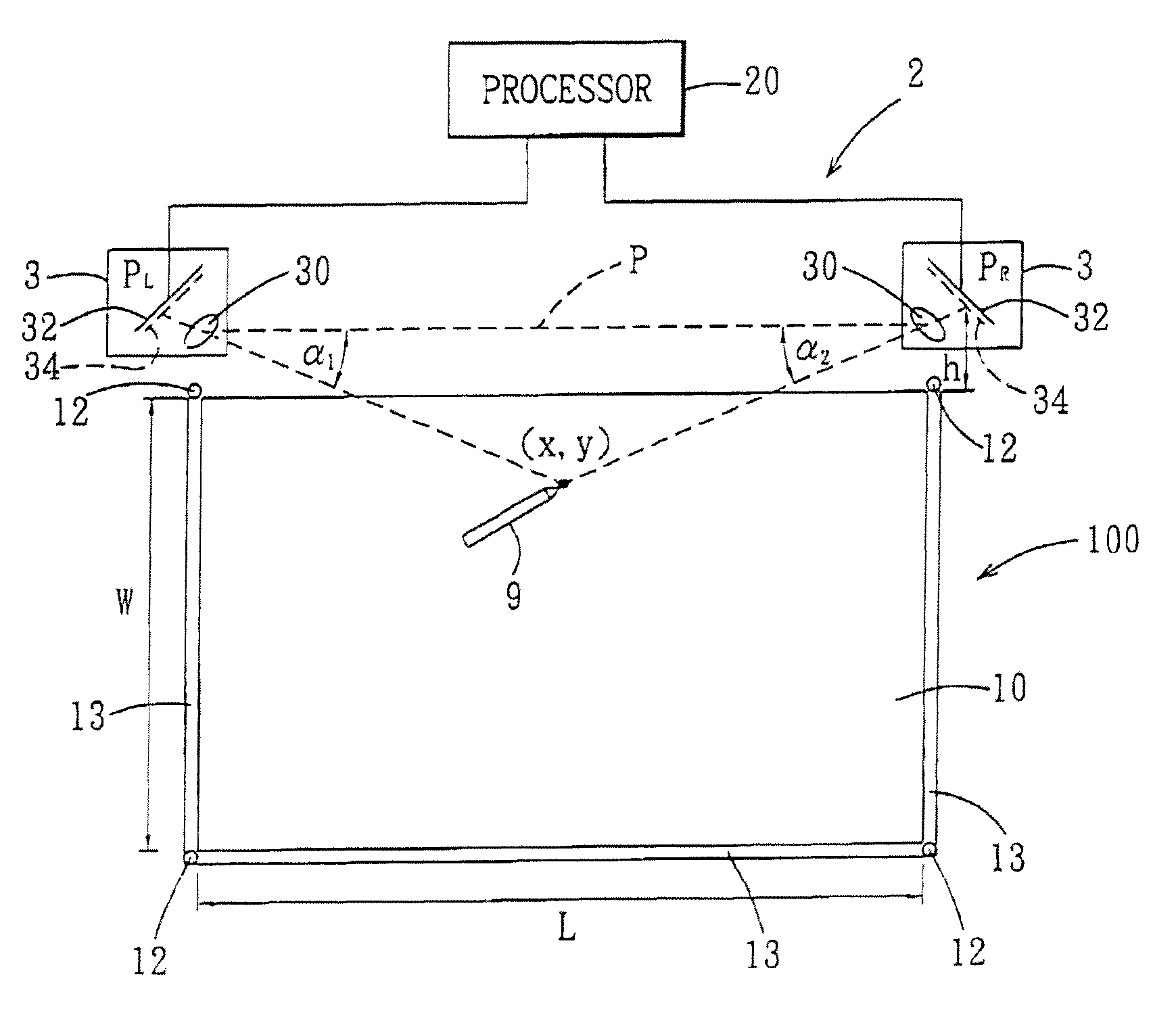
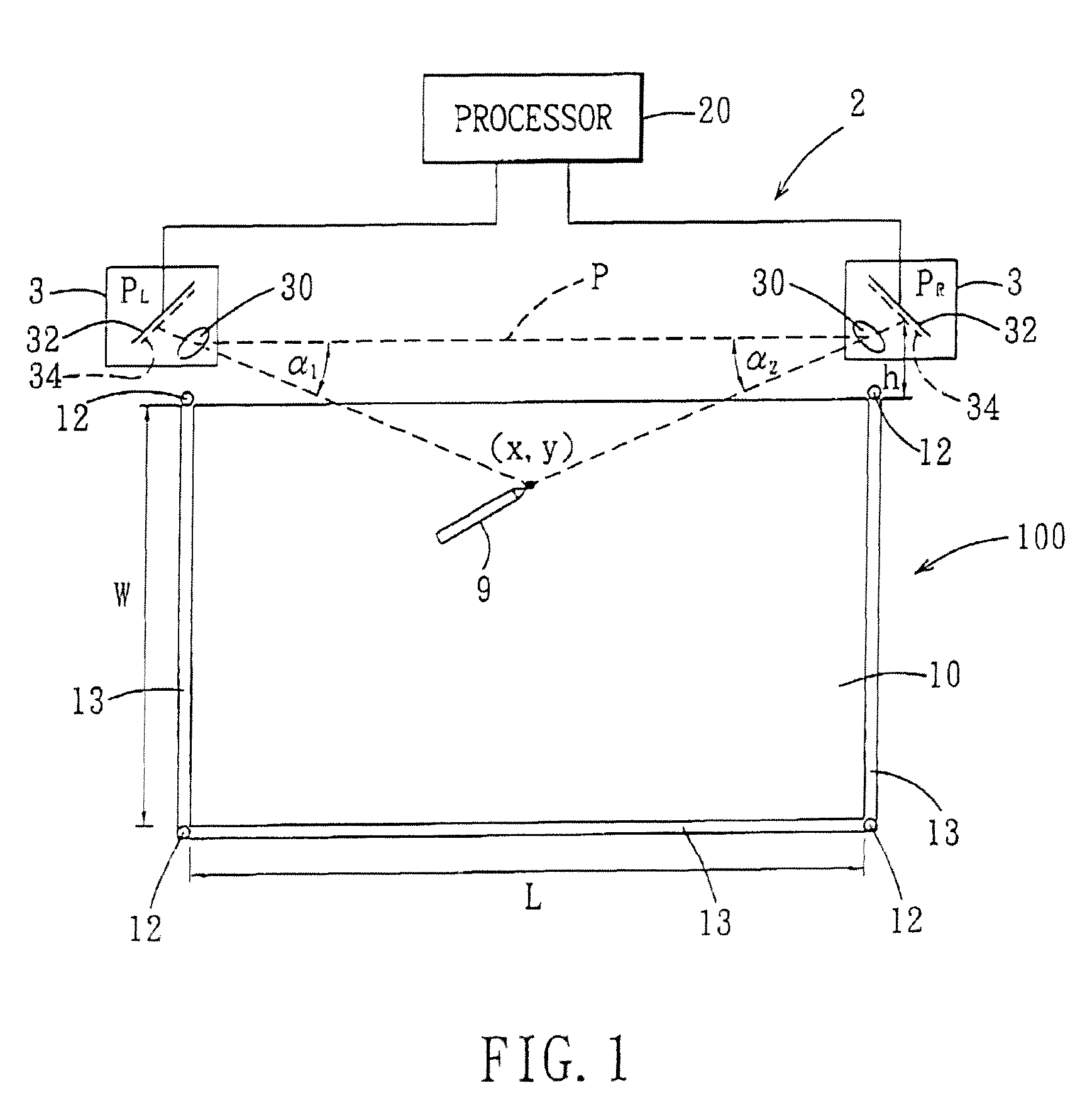
[0024]Referring to FIG. 1, a preferred embodiment of an optical touch panel 100 according to the present invention includes a touch surface 10, which is generally a planar surface, for contact with an object 9, a light source module, and a detecting device 2. The light source module is disposed to define a light curtain region on one side of the touch surface 10, and includes a plurality of light sources 12 for emitting invisible light, for example infrared LEDs, and a plurality light guides 13 for uniformly distributing the light emitted from the light sources 12 across the side of the touch surface 10. The touch surface 10 is substantially rectangular in shape and has a length L and a width W.

[0025]The detecting device 2 includes two light detectors 3, and a processor 20. The light detectors 3 are disposed respectively adjacent to a first corner and a second corner, wherein the first corner and the second corner are located at two ends of a long edge of the touch surface 10. Each ...


PUM


Abstract

A coordinate information correction method for an optical touch panel includes: a) determining a set of to-be-corrected included angle values according to output signals received from light detectors, each of the to-be-corrected included angle values representing an included angle between a base line and a connecting line that extends from a respective one of the light detectors to a location of an object in a light curtain region; b) calculating a set of correction values, each of which is a finite order function of a respective one of the to-be-corrected included angle values; c) calculating a set of corrected included angle values from the set of to-be-corrected included angle values and the set of correction values; and d) generating corrected coordinate information associated with the location of the object in the light curtain region from the corrected included angle values.

Description

CROSS-REFERENCE TO RELATED APPLICATION[0001]This application claims priority of Taiwanese Application No. 099126915, filed on Aug. 12, 2010.BACKGROUND OF THE INVENTION[0002]1. Field of the Invention[0003]The present invention relates to a correction method for a touch panel, more particularly to a coordinate information correction method for an optical touch panel.[0004]2. Description of the Related Art[0005]Conventional touch panels include resistive touch panels, capacitive touch panels, and optical touch panels. The resistive touch panel, compared to the capacitive touch panel, is less expensive but has a slower response.[0006]One example of an optical touch panel uses an infrared LED module, which emits infrared beams, and photodetector pairs around a periphery of the touch panel for detecting an interruption in a pattern of the infrared beams. Another optical touch panel uses an infrared backlight module and at least two image sensors (CCD or CMOS sensor elements) placed around...

Claims


Application Information

Patent Timeline
Patent Type & Authority Patents(United States)
IPC IPC(8): G06F3/042
CPCG06F3/0418G06F3/0428
Inventor CHEN, JAU-YUTING, YU-WEN
Owner DYNA IMAGE CORPORATION
Why Eureka
Try Eureka