A thrust transducer for a pulse detonation engine

A technology of pulse detonation and engine, applied in the direction of mechanical equipment, power plant type, power plant construction, etc., can solve the problems of reduced working life, increased accident probability, narrowed engine stable working range, etc., to increase high frequency, reduce shaft effect of displacement

Active Publication Date: 2019-01-25
NORTHWESTERN POLYTECHNICAL UNIV
View PDF12 Cites 1 Cited by
  • Summary
  • Abstract
  • Description
  • Claims
  • Application Information

AI Technical Summary

Problems solved by technology

But this can bring new problem again: 1. the upper limit of frequency is limited by factors such as detonation tube actual size, valve switch, reactant supply speed, control program reaction time and reactant detonation rate, can not improve without limit; 2. .Increasing the knocking frequency will reduce the stable working range of the engine; 3. High-frequency and large-scale impact will make the material very easy to fatigue, greatly reduce the working life, and increase the probability of accidents

Method used


Image

  • A thrust transducer for a pulse detonation engine
  • A thrust transducer for a pulse detonation engine
  • A thrust transducer for a pulse detonation engine

Examples


Embodiment Construction

[0033] The embodiments described below with reference to the accompanying drawings are exemplary, and are intended to explain the present invention, but should not be construed as limiting the present invention.

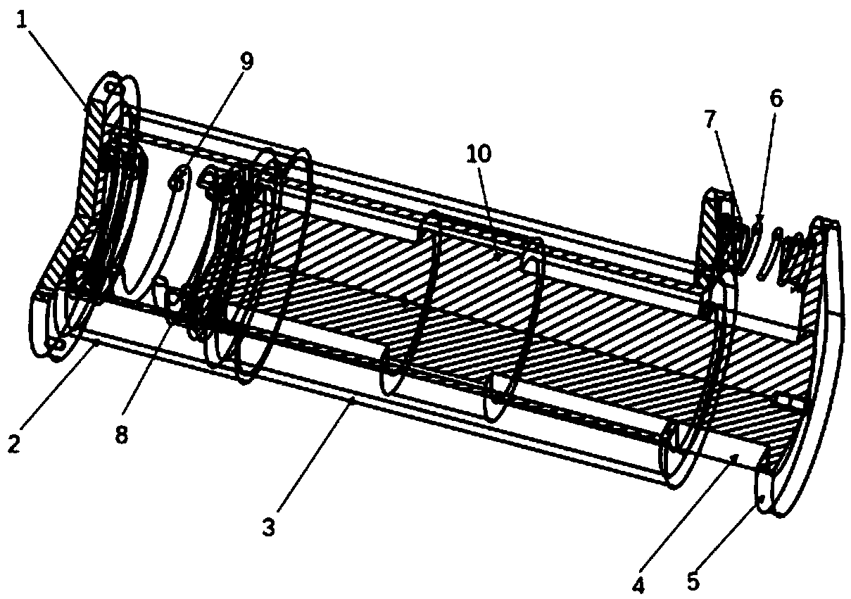
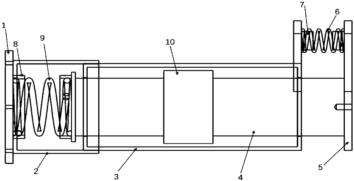
[0034] Reference figure 1 with figure 2 , A thrust converter of a pulse detonation engine of the present invention includes an aircraft mounting seat 1, a spring cavity 2, a linear viscous damper, an engine mounting seat 5, a parallel spring 6 and a series spring 9; inside the linear viscous damper The damping oil cylinder 3, the piston rod 4 and the piston 10 are installed coaxially. The damping oil cylinder 3 is a hollow cylindrical structure with through holes at the center of its two ends. The piston rod 4 is installed through the two through holes; the piston 10 is installed The outer peripheral surface at the center of the piston rod 4 is in clearance fit with the inner surface of the damping cylinder 3;

[0035] One end of the linear viscous damper is fixed to th...


PUM


Abstract

The invention discloses a thrust converting device of a pulse detonation engine, comprising an aircraft mount, a spring cavity, a linear viscous damper, an engine mount, a parallel spring and a seriesspring; the thrust converting device comprises an aircraft mount, a spring cavity, a linear viscous damper, an engine mount, a parallel spring and a series spring. The thrust conversion device is connected with the aircraft and the pulse detonation engine through an aircraft mount and an engine mount. The linear viscous damper is designed as a symmetrical double-output rod clearance damper, so that the damping property thereof does not change with the change of the motion direction, and is convenient to control. Adopting the structure design of two springs mounted side by side not only improves its ability to isolate high frequency, periodic, pulse-type and large peak-to-peak thrust, but also reduces the axial displacement of the engine. Pulse detonation engine produces periodic, pulsed,large peak-to-peak thrust transfer to the engine mount, through the spring storage energy, damper energy consumption, and ultimately converted into a small fluctuation of the quasi-steady force, through the mount transfer to the aircraft.

Description

Technical field [0001] The invention belongs to the field of pulse detonation engines, and specifically relates to a thrust converter of a pulse detonation engine. Background technique [0002] Pulse detonation engine is a new concept aircraft engine that uses high temperature and high pressure gas generated by intermittent detonation waves to generate thrust. Detonation waves can be roughly considered to be composed of supersonic shock waves and tightly coupled thin flames or reaction zones. Due to the extremely high gas pressure (greater than 15 to 55 atmospheres), the gas temperature (greater than 2800K) and the extremely fast propagation speed (Mach number greater than 4) of the detonation wave, it is very attractive to the propulsion system. The detonation process is thermodynamically closer to the constant volume cycle than the isobaric combustion of the ordinary deflagration-based propulsion system, so it has a higher thermodynamic efficiency. In addition, pulse detonati...

Claims


Application Information

Patent Timeline
Patent Type & Authority Applications(China)
IPC IPC(8): B64D27/26B64D27/02F02K7/02
CPCB64D27/02B64D27/26F02K7/02
Inventor 郑龙席刘坤王凌羿李勍
Owner NORTHWESTERN POLYTECHNICAL UNIV
Why Eureka
Try Eureka