
An Equalization Filter with High Gain and High Compensation Range

A technology of equalizing filters and amplifiers, applied in impedance networks, digital technology networks, electrical components, etc., to solve problems such as clock dependence, low signal rate, and large circuit footprint.

Active Publication Date: 2017-02-22
NANJING UNIV OF POSTS & TELECOMM
View PDF2 Cites 0 Cited by
  • Summary
  • Abstract
  • Description
  • Claims
  • Application Information

AI Technical Summary

Problems solved by technology

Digital equalizers can achieve equalization effects through different algorithms, but they have disadvantages such as clock dependence, low signal rate that can be equalized, and large circuit footprint.

Method used


Image

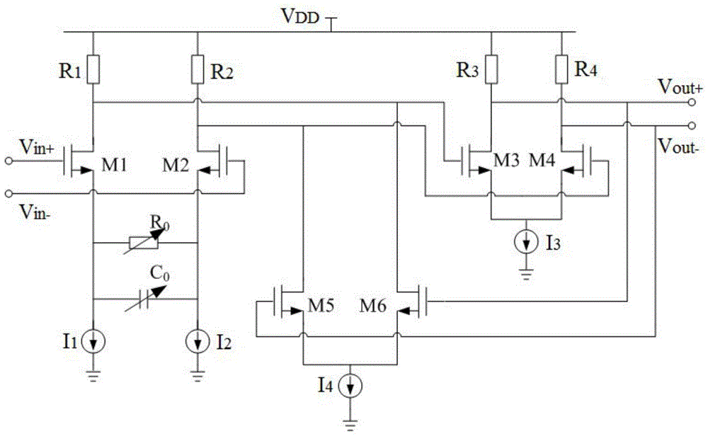
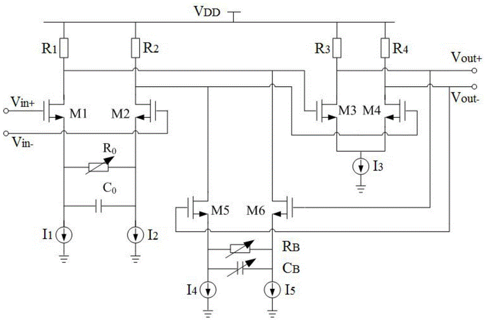
  • An Equalization Filter with High Gain and High Compensation Range
  • An Equalization Filter with High Gain and High Compensation Range
  • An Equalization Filter with High Gain and High Compensation Range

Examples


Embodiment Construction

[0019] In order to further illustrate the advantages of the present invention, the specific implementation manner and circuit structure of the present invention will be described in detail below in conjunction with the accompanying drawings.

[0020] The equalization filter is composed of a two-stage cascaded differential amplifier and a first-stage feedback differential amplifier;

[0021] Among them, the first pair of NMOS transistors M1, M2, the first pair of variable resistors and variable capacitors R 0 , C 0 , the first pair of resistors R 1 ,R 2 Form the first differential amplifier; the first pair of resistors R 1 ,R 2 respectively connected to the drain of the first pair of NMOS transistors M1, M2 and V DD between the load, the first pair of variable resistors and variable capacitors R 0 , C 0 Connect across the sources of the first pair of NMOS transistors M1 and M2, and the gates of the first pair of NMOS transistors M1 and M2 are respectively connected to th...


PUM


Abstract

The invention discloses an equalizing filter with high gain and high compensation range. The equalization filter consists of two stages of cascaded differential amplifiers and one stage of feedback differential amplifiers. The invention improves the structure of the traditional active negative feedback equalization filter, so that the feedback amount of the negative feedback can be adjusted, so as to improve the variable range of the high-frequency gain, thereby increasing the compensation ability of the equalizer. In order to realize the adjustable feedback amount, the source negative feedback technology is introduced into the ordinary feedback differential amplifier, that is, a parallel variable resistor and a variable capacitor are added to the source of the feedback differential pair. By controlling the size of the variable resistor and the variable capacitor, the low-frequency and high-frequency feedback can be changed respectively, thereby controlling the low-frequency, high-frequency gain and its adjustable range. In addition, the present invention can also achieve higher circuit performance through multi-stage cascading. The invention has the advantages of large bandwidth, strong gain compensation ability, large gain compensation range and the like.

Description

technical field [0001] The invention belongs to the field of semiconductor integrated circuit design, and mainly relates to an equalizing filter with high gain and high compensation range. Background technique [0002] Modern communication systems have higher and higher requirements for communication rates. For example, the transmission rates of bus interfaces such as USB3.0, HDMI1.4, SATA3.0, and PCIExpress have reached several Gb / s or even more than ten Gb / s. At such a high data transmission rate, the high-frequency loss of the data transmission channel caused by the skin effect and dielectric loss will have a serious impact on the integrity of the signal, and it is easy to cause Inter-Symbol Interference (ISI). For example, at 3.125GHz, when the channel loss is greater than 6dB, the attenuation of 6.25Gb / s data at the receiving end will exceed 50%. At this time, the signal eye diagram is completely closed and the data becomes unrecoverable. [0003] In order to overcome ...

Claims


Application Information

Patent Timeline
Patent Type & Authority Patents(China)
IPC IPC(8): H03H17/02
Inventor 张长春赵宗良李志贞赵江刘蕾蕾郭宇锋
Owner NANJING UNIV OF POSTS & TELECOMM
Learn More