Digital multimeter having remote display with automatic communication binding

a digital multimeter and display unit technology, applied in the field of digital multimeters, can solve the problems of difficult to view the lcd display and undesired remote display

Active Publication Date: 2013-02-12
JOHN FLUKE MFG CO INC
View PDF34 Cites 30 Cited by
  • Summary
  • Abstract
  • Description
  • Claims
  • Application Information

AI Technical Summary

Problems solved by technology

Often, however, the shelf may be in a position making it difficult to view the LCD display.
If this occurs, it is possible that the remote display could undesirably show results from a DMM different from the one being operated by the user.

Method used


Image

  • Digital multimeter having remote display with automatic communication binding
  • Digital multimeter having remote display with automatic communication binding
  • Digital multimeter having remote display with automatic communication binding

Examples


Embodiment Construction

[0022]It is to be understood by one of ordinary skill in the art that the present discussion is a description of exemplary embodiments only, and is not intended as limiting the broader aspects of the present invention, which broader aspects are embodied in the exemplary constructions.

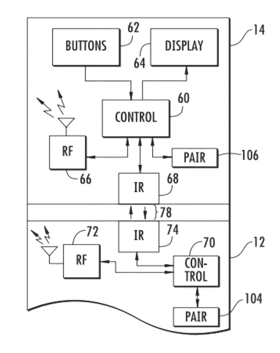
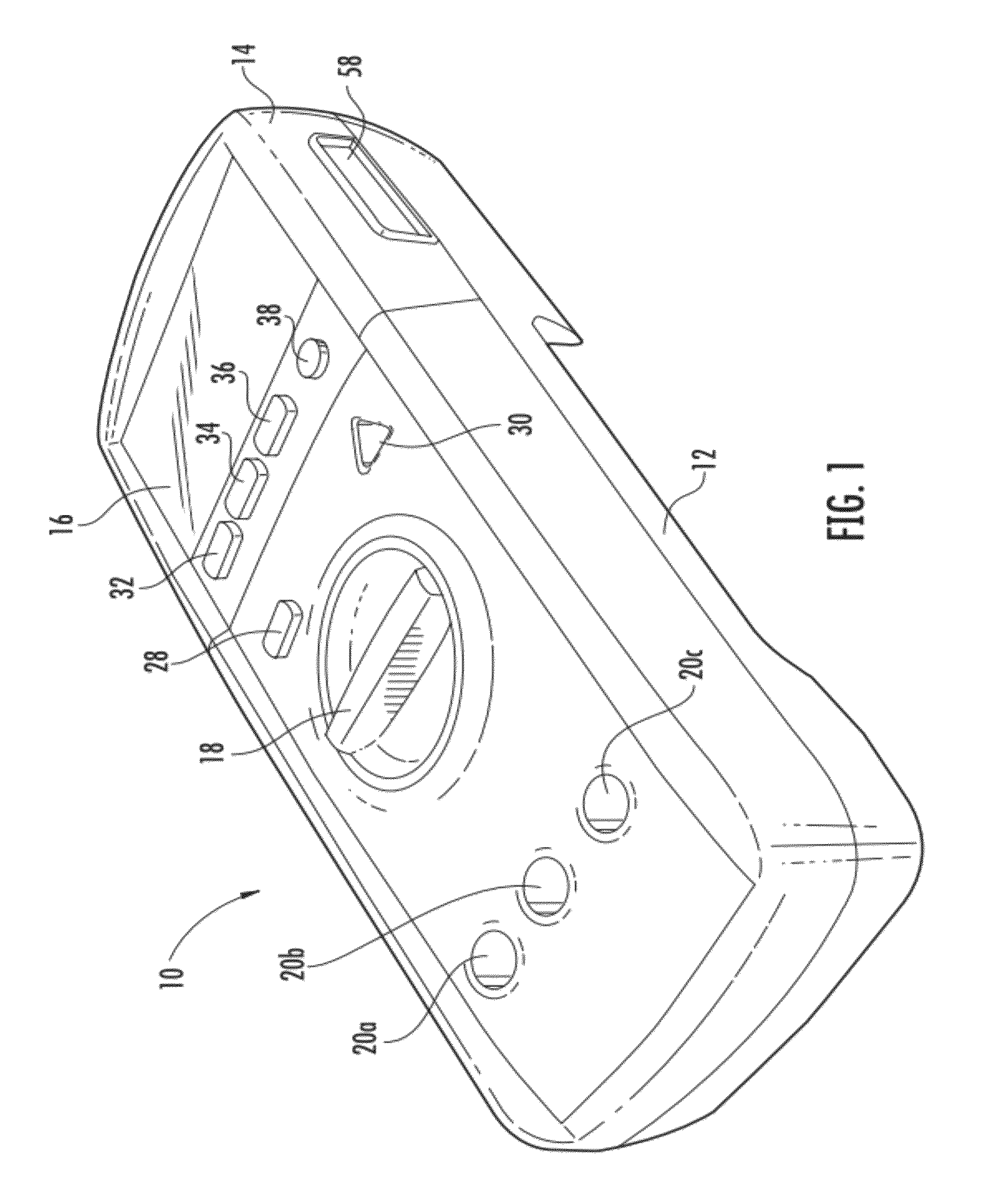
[0023]FIG. 1 illustrates a digital multimeter (DMM) 10 constructed in accordance with an embodiment of the present invention. Multimeter 10 comprises a base unit 12 and a remote display unit 14. The housing of base unit 12 defines an interior cavity in which various internal components are located. In this embodiment, the housing of base unit 12 is preferably formed having two or more housing members which are assembled together to form the interior cavity. Preferably, these housing members may be molded of high impact rigid plastic material. In some cases, it may be desirable to overmold a softer polymeric material on at least portions of the rigid plastic material to enhance gripability and user comfo...


PUM


Abstract

An electrical test instrument comprising a base unit having a first communication address. A remote display unit separate from the base unit and having a second communication address is also provided. Communication circuitry is operative to provide electrical communication in a first RF mode between the base unit and the remote display unit as a bound communication pair based on the first and second communication addresses. The communication circuitry is further operative to operate selectively in a second secure communication mode. The first and second communication addresses are exchanged in the second secure communication mode to establish the bound communication pair for subsequent communication in the first RF mode. In some exemplary embodiments, the second communication mode is an optical communication mode (e.g., an IR communication mode).

Description

BACKGROUND OF THE INVENTION[0001]The present invention relates generally to digital multimeters. More particularly, the invention relates to a digital multimeter having a remote display unit which automatically binds for communication with a base unit.[0002]Digital multimeters (DMMs) function to measure a number of electrical parameters as needed for service, troubleshooting and maintenance. Such parameters may include AC voltage and current, DC voltage and current, resistance and continuity. In some cases, a DMM may measure other parameters such as capacitance and temperature.[0003]A DMM will often be configured as a hand-held unit having a rotary knob by which various functions are selected. A plurality of lead jacks are provided in the case (i.e., housing) of the unit for connection of test leads. The specific jack used may depend on the function that has been selected. An LCD display provides a reading of the tested parameter. Details regarding the construction and operation of ...

Claims


Application Information

Patent Timeline
Patent Type & Authority Patents(United States)
IPC IPC(8): H04B10/00
CPCG08C17/02G08C23/04H04B10/22G01R15/125G01R1/025H04B10/114H04B10/1143H04W76/14H04W76/23H04B10/11
Inventor HUDSON, JEFFREY C.WETZEL, NATHANIEL J.VETTER, GLEN HOWARD
Owner JOHN FLUKE MFG CO INC
Why Eureka
Try Eureka