Wiper blade for vehicle

a technology for wiper blades and vehicles, applied in the field of wiper blades for vehicles, can solve the problems of affecting the appearance of the outer surface, damage to the primary cover, etc., and achieve the effects of improving the performance of the wiper blade, improving the assemblability and hinge strength, and stable connection structur

Active Publication Date: 2013-02-19
HYUNDAI MOTOR CO LTD +2
View PDF8 Cites 9 Cited by
  • Summary
  • Abstract
  • Description
  • Claims
  • Application Information

AI Technical Summary

Benefits of technology

[0015]Various aspects of the present invention are directed to provide a wiper blade for a vehicle, which improves the assemblability and hinge strength between a primary cover and a secondary lever by further providing structures such as an adapter and a hinge member and provides a stable connection structure between the primary cover and the secondary lever by increasing the contact area between the primary cover and the adapter, thus improving the performance of the wiper blade.
[0022]According to various aspects of the wiper blade of the present invention, the primary cover and the secondary lever are slidably assembled and connected to each other by the use of the adapter, and the secondary lever and the adapter are hinge-connected by means of a rivet, thus improving the assemblability and hinge strength.
[0023]Moreover, the present invention provides a stable connection structure between the primary cover and the secondary lever by increasing the contact area between the primary cover and the adapter, thus preventing vibration during wiping of the glass surface and improving the performance of the wiper blade.
[0024]Further, the present invention improves the mass productivity of the wiper by the improvement of the assemblability. In addition, with the use of the adapter, it is possible to prevent a gap between the primary cover and the secondary lever, which may be caused during the operation of the wiper, by assembling the primary cover and the secondary lever in a slidable manner in the lateral direction, in a forcible manner in the vertical direction, or in a riveting manner, thus increasing the durability.

Problems solved by technology

However, as shown in FIG. 2, the conventional wiper blade has the problems that the primary cover 10 may be damaged as the secondary lever 20 is forcibly inserted into a hinge (injection molded) 11 of the primary cover 10 in the vertical direction, and thereby the outer appearance is impaired.

Method used


Image

  • Wiper blade for vehicle
  • Wiper blade for vehicle
  • Wiper blade for vehicle

Examples


Embodiment Construction

[0041]Reference will now be made in detail to various embodiments of the present invention(s), examples of which are illustrated in the accompanying drawings and described below. While the invention(s) will be described in conjunction with exemplary embodiments, it will be understood that present description is not intended to limit the invention(s) to those exemplary embodiments. On the contrary, the invention(s) is / are intended to cover not only the exemplary embodiments, but also various alternatives, modifications, equivalents and other embodiments, which may be included within the spirit and scope of the invention as defined by the appended claims.

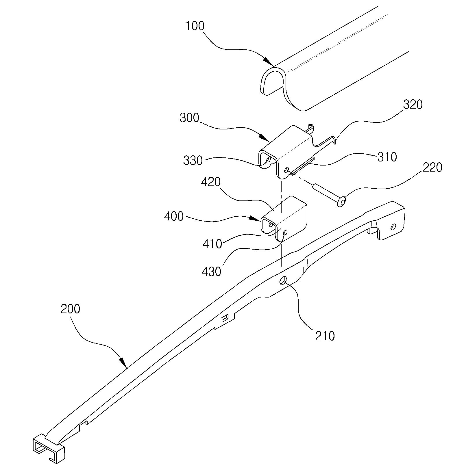
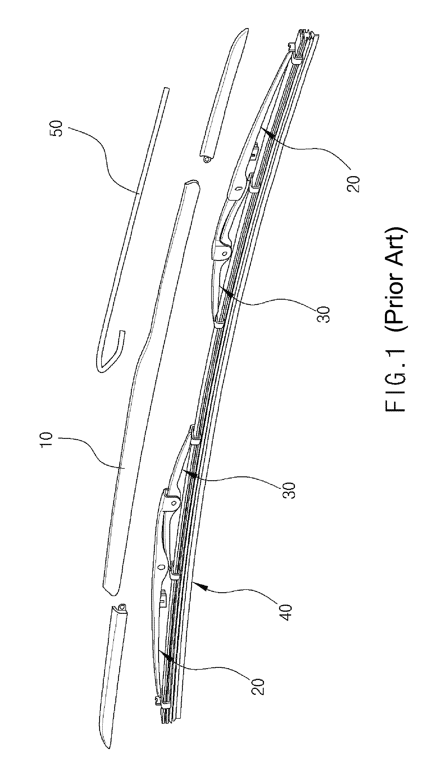
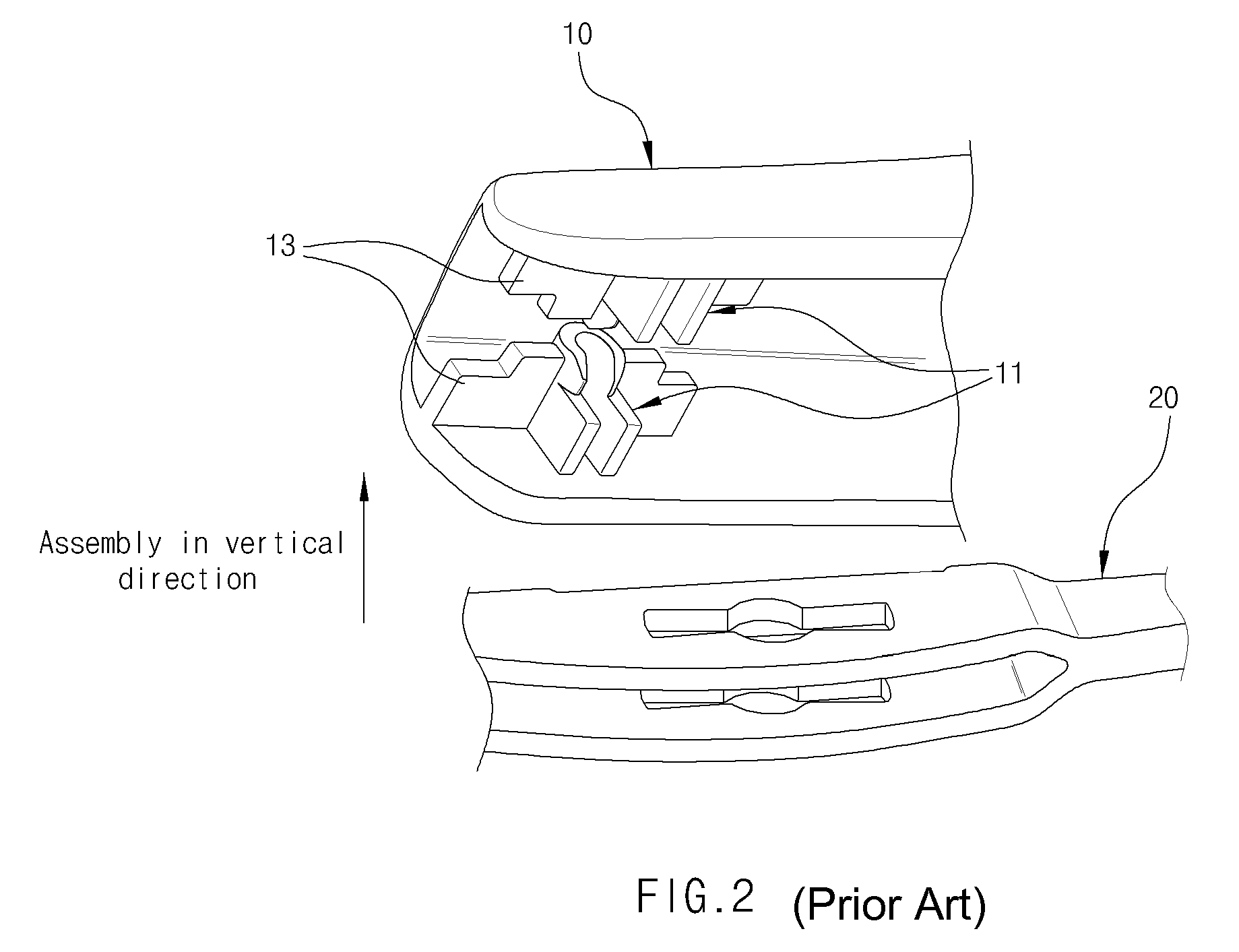
[0042]The present invention provides an exemplary wiper blade for a vehicle which is used to remove water and other substances from the surface of a front or rear glass (i.e., a windshield glass or rear window). The exemplary wiper blade of the present invention improves the assemblability and hinge strength between a primary cover 10...


PUM


Abstract

A wiper blade for a vehicle may include a secondary lever including a lever rivet hole, an adapter including a guide rib formed in the longitudinal direction thereof, a locking projection formed at the rear thereof, and an adapter rivet hole, a primary cover including a guide groove formed in the longitudinal direction thereof and into which the guide rib of the adapter is inserted, and a locking groove into which the locking projection of the adapter is inserted, and a hinge member penetrating the lever rivet hole and the adapter rivet hole and pivotally coupling the adapter and secondary lever.

Description

CROSS-REFERENCE TO RELATED APPLICATION[0001]The present application claims priority to Korean Patent Application No. 10-2009-0097459 filed on Oct. 13, 2009, the entire contents of which are incorporated herein for all purposes by this reference.BACKGROUND OF THE INVENTION[0002]1. Field of the Invention[0003]The present disclosure relates to a wiper blade for a vehicle which is used to remove water and other substances from the surface of a glass. More particularly, it relates to a wiper blade for a vehicle which improves the assemblability and hinge strength to prevent vibration during wiping of the glass surface, thereby improving the operational performance of the wiper blade.[0004]2. Description of Related Art[0005]In general, a wiper is mounted on the outside surface of a windshield glass or a rear window of a vehicle to remove rainwater or foreign substances from the glass surface during a rainy or snowy day, thus ensuring a driver's visibility. The driving force of a drive mot...

Claims


Application Information

Patent Timeline
Patent Type & Authority Patents(United States)
IPC IPC(8): A47L1/00B60S1/02
CPCB60S1/3801B60S2001/3815B60S1/32B60S1/40
Inventor KIM, ILL SOOKANG, CHANG KYWOO, CHANG OANLEE, JONG HEONAN, JAE HYUCK
Owner HYUNDAI MOTOR CO LTD
Why Eureka
Try Eureka