Thermally driven deformable micromirror

A micromirror-shaped, thermally driven technology, applied in optical components, optics, instruments, etc., can solve the problems of complex preparation process, small deformation, and high driving voltage, and achieve a simplified preparation process, low production difficulty, and improved heating efficiency. Effect

Active Publication Date: 2020-03-27
BEIJING INSTITUTE OF TECHNOLOGYGY +1
View PDF5 Cites 7 Cited by
  • Summary
  • Abstract
  • Description
  • Claims
  • Application Information

AI Technical Summary

Problems solved by technology

However, the current micro-deformable mirrors have the disadvantages of high driving voltage and small deformation, and the preparation process is relatively complicated.

Method used


Image

  • Thermally driven deformable micromirror
  • Thermally driven deformable micromirror
  • Thermally driven deformable micromirror

Examples


Embodiment Construction

[0032] The present invention will be described in detail below with reference to the accompanying drawings and examples.

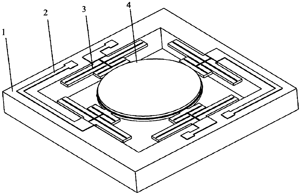
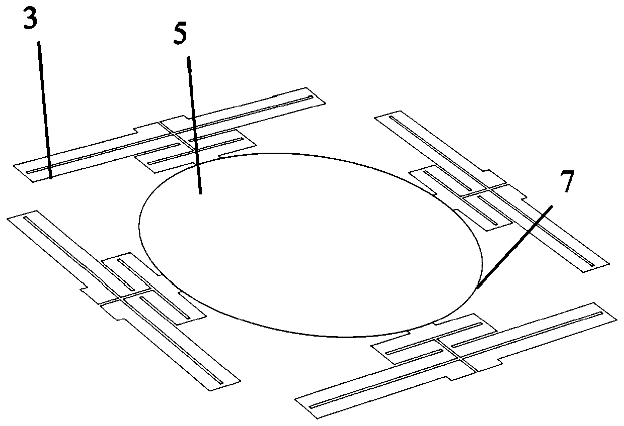
[0033] as attached figure 1 As shown, the present invention provides a thermally driven deformable micromirror. The micromirror is made up of a lens 4, an electrode 2, a beam 3 and a silicon structural frame 1, and four beams 3 support the circular lens 4 in the air on the silicon structure. The center of the structural frame 1, as attached figure 2 As shown, the lens 4 is divided into three layers from top to bottom, which are aluminum reflective layer 5, silicon dioxide layer 6 and silicon layer 7, as shown in the attached image 3 and 4 As shown, the silicon layer 7 of the beam 3 and the lens 4 is integrally formed of the same material, the silicon structure frame 1 and the beam 3 are insulated by a silicon dioxide layer 6, and the electrode 2 is arranged on the surface of the silicon structure frame 1 and the support The beam 3 is connected, and af...


PUM


Abstract

The invention discloses a thermally driven deformable micromirror, and belongs to the technical field of adaptive optical systems. The micro-mirror is composed of a lens, an electrode, a supporting beam and a silicon structure frame. The lens is suspended and supported in the center of the silicon structure frame by the support beam; the lens is divided into three layers from top to bottom, namely, a metal reflecting layer, a silicon dioxide layer and a silicon layer; the supporting beam and the silicon layer of the lens are integrally formed by the same material, the silicon structural frameand the supporting beams are insulated by the silicon dioxide layer, the electrode is arranged on the surface of the silicon structural frame and connected with the supporting beam, after the electrode is powered on, the supporting beam and the lens form a current loop and emit heat, and the lens deforms due to different thermal expansion coefficients of metal and silicon. The heating temperaturesof two different materials, namely metal and silicon, are controlled by electrifying, so that the purpose of mirror surface deformation is achieved.

Description

technical field [0001] The invention relates to a deformable micromirror structure, in particular to a thermally driven deformable micromirror, which belongs to the technical field of adaptive optical systems. Background technique [0002] A micromirror is a miniaturized mirror. Since Texas Instruments successfully produced a commercial digital micromirror, various types of micromirrors have sprung up like mushrooms after rain. The development of micromirrors, on the one hand, benefits from the progress of Micro-Electromechanical Systems (MEMS) technology, including surface technology, bulk silicon processing technology, self-assembly technology, etc. On the other hand, market demand is also driving the development of micromirror technology. Most micromirrors are micromirrors that drive the lens to move by the driving arm. For example, the electrostatic micromirror uses an array of comb teeth to drive the lens to deflect; the piezoelectric micromirror uses the reverse piezo...

Claims


Application Information

Patent Timeline
Patent Type & Authority Applications(China)
IPC IPC(8): G02B26/06
CPCG02B26/06
Inventor 汤跃徐立新李建华王鹏谢会开
Owner BEIJING INSTITUTE OF TECHNOLOGYGY
Why Eureka
Try Eureka