Copper terminal and aluminum wire joint and magnetic induction welding method thereof

A welding method and technology of copper terminals, which are applied in the field of wire harnesses, can solve the problems of inability to meet the industrial-grade preparation requirements of copper terminals and aluminum wire joints, the inability to directly apply copper terminals and aluminum wire joints, and the inability to solve copper and aluminum welding, etc. Achieve ideal welding effect, save material and time costs, and save manufacturing costs

Active Publication Date: 2017-09-01
JILIN ZHONG YING HIGH TECH CO LTD
View PDF5 Cites 4 Cited by
  • Summary
  • Abstract
  • Description
  • Claims
  • Application Information

AI Technical Summary

Problems solved by technology

Therefore, this patented method has great limitations in the use of copper terminals and aluminum wire joints in the wiring harness industry
[0005] (2) This technology cannot be directly applied to the preparation of copper terminals and aluminum wire joints
The technique is to weld two undefined classes of metals together, and the welding method described in this patent does not address the particularities of copper and aluminum welding, or in the field of wire harnesses, copper terminals and aluminum wires
The direct contact between the copper terminal and the aluminum wire will cause electrochemical corrosion in the wiring harness e

Method used


Image

  • Copper terminal and aluminum wire joint and magnetic induction welding method thereof
  • Copper terminal and aluminum wire joint and magnetic induction welding method thereof
  • Copper terminal and aluminum wire joint and magnetic induction welding method thereof

Examples


Embodiment 1

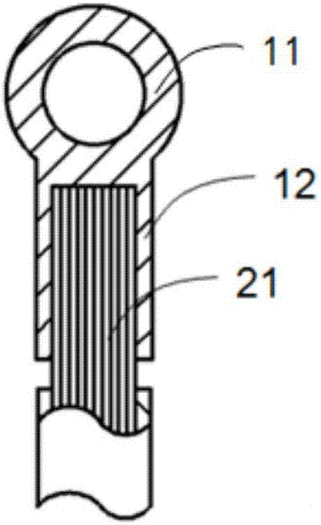
[0058] This embodiment is one of the preferred implementations of the joint between the copper terminal and the aluminum wire of the present invention. Such as figure 1 As shown, the copper terminal is divided into a connecting piece 12, and a functional piece 11 connected to the connecting piece, and the aluminum core of the aluminum wire 21 is connected to the connecting piece of the copper terminal; preferably, the aluminum guiding core Extend or not extend to the feature.

[0059] Preferably, the material of the copper terminal is copper or copper alloy; preferably, the material of the aluminum core of the aluminum wire is aluminum or aluminum alloy.

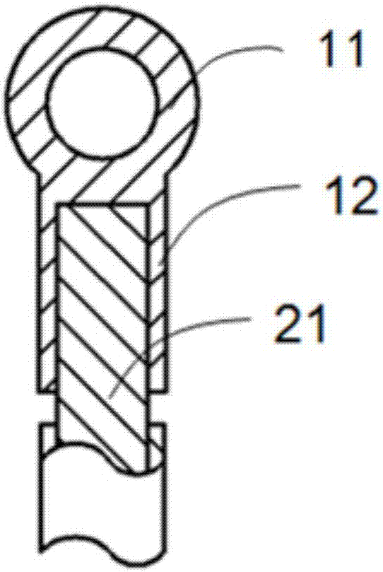
[0060] In this embodiment, the aluminum wire is a multi-core aluminum wire. In other implementations, the aluminum wire can also be a solid aluminum wire, such as figure 2 shown.

[0061] In one of the preferred implementations, the shape of the connector is flat or arc-shaped or wing-shaped open or circular closed or po...

Embodiment approach

[0077] This embodiment is a more preferred implementation of the magnetic induction welding method between copper terminals and aluminum wires of the present invention, which includes the following steps:

[0078] S1: Assemble the aluminum guide core and the copper terminal connector, the distance between the aluminum guide core and the copper terminal connector is 0-10mm; preferably, the distance between the aluminum guide core and the copper terminal connector is 0 -3mm;

[0079] S2: Welding the aluminum guide core and the copper terminal connector together by using a magnetic induction welding method, so that the outer surface of the aluminum guide core is connected to the surface of the copper terminal connector.

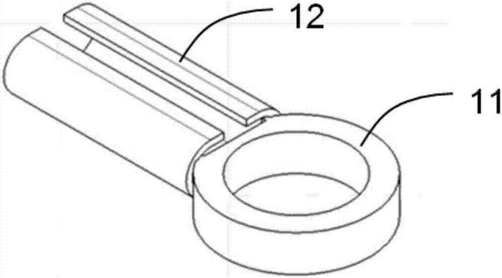
[0080] Before S1, remove the insulation layer of the aluminum wire according to the size of the terminal connector; then assemble the connecting part of the aluminum wire with the insulation layer removed and the copper terminal. Such as image 3 Shown is a sc...

Embodiment 3

[0095] This embodiment is another preferred embodiment of the magnetic induction welding method between copper terminals and aluminum wires and the joint structure formed by the present invention. The difference between this embodiment and the above-mentioned embodiments lies in:

[0096] The S1 further includes the following step: adding a spacer metal layer between the welding end of the aluminum wire and the copper terminal connector. Since copper and aluminum belong to different elements, the metal inertness of copper is greater than that of aluminum, and the electrode potential difference between copper and aluminum is relatively large (+0.337 for copper and -1.662 for aluminum). When the two metals are in direct contact, in the air and water Under the action, aluminum will gradually lose electrons and form an electrochemical reaction, causing corrosion of aluminum wires and reducing the service life of the wiring harness. In severe cases, accidents (such as burning cars) ...


PUM

PropertyMeasurementUnit
Thicknessaaaaaaaaaa
Thicknessaaaaaaaaaa
Thicknessaaaaaaaaaa

Abstract

The invention discloses a copper terminal and aluminum wire joint and a magnetic induction welding method thereof. The copper terminal of the joint is divided into a connector and a functional part connected with the connector. The aluminum guide core of the aluminum wire is connected with the connector of the copper terminal. The aluminum guide core extends or does not extend to the functional part. The magnetic induction welding method comprises the steps that S1 the aluminum guide core after insulating layer stripping and the connector of the copper terminal are assembled; and S2 the welding end of the aluminum wire and the connector of the copper terminal are welded together through magnetic induction welding. According to the technical scheme, copper and aluminum are welded; the electrical performance and the mechanical performance are better; terminals of terminal connectors of different shapes are connected with the aluminum wire; and the preparation efficiency and quality are improved.

Description

technical field [0001] The invention relates to the field of wire harnesses, in particular to a joint between a copper terminal and an aluminum wire and a magnetic induction welding method thereof. Background technique [0002] In the common connection technology of the existing wire harness, the connection method of the terminal and the wire is mainly crimping, that is, the guide core of the wire is put into the connector of the terminal, and the terminal and the wire are crimped in a mechanical way using a terminal crimping mold. Together. However, for the combination of copper terminals and aluminum wires, the traditional crimping method cannot solve the electrochemical reaction between the aluminum wires and copper terminals over time, resulting in poor mechanical and electrical properties of the copper terminals and aluminum wire joints. decline. Therefore, for the connection of copper terminals and aluminum wire joints, the method of crimping is difficult to be appli...

Claims


Application Information

Patent Timeline
IPC IPC(8): H01R4/62H01R11/12H01R43/02
CPCH01R4/625H01R11/12H01R43/02H01R4/184H01R43/0207H01R4/023B23K13/01B23K2101/38B23K2103/10B23K2103/12B23K2103/18
Inventor 不公告发明人
Owner JILIN ZHONG YING HIGH TECH CO LTD
Why Eureka
Try Eureka