Electronic card connector

A technology for electronic cards and connectors, applied in the direction of connection, fixed connection, circuit, etc., can solve the problems of increasing production cost, restricting conductive terminals in multiple directions, and scrapping products, etc., to improve product yield, good welding effect, and improve The effect of coplanarity requirements

Inactive Publication Date: 2010-02-17
FOXCONN (KUNSHAN) COMPUTER CONNECTOR CO LTD +1
View PDF0 Cites 6 Cited by
  • Summary
  • Abstract
  • Description
  • Claims
  • Application Information

AI Technical Summary

Problems solved by technology

[0003] Common electronic card connectors, such as Express card connectors, although a fixed structure is provided at the connection end where the conductive terminals are connected to the printed circuit board, the fixed structure is only a series of barrier blocks between the conductive terminals, and only for mutual protection between the conductive terminals. Partially isolated in the lateral direction, it cannot confine the conductive terminals in multiple orientations
Therefore, during the installation and movement process of installing the electronic card connector on the printed circuit board, because the terminals are relatively small and closely arranged, under the condition of being squeezed by external force, the connection ends of the conductive terminals are easily deformed or misplaced, which will affect its The accuracy of the connection with the printed circuit board, that is, the connection end of the conductive terminal cannot be accurately docked with the corresponding soldering point on the printed circuit board
In addition, this will make the product scrapped and increase the production cost, which does not conform to the development trend of cost-saving, stable and reliable electrical connectors

Method used


Image

  • Electronic card connector
  • Electronic card connector
  • Electronic card connector

Examples


Embodiment Construction

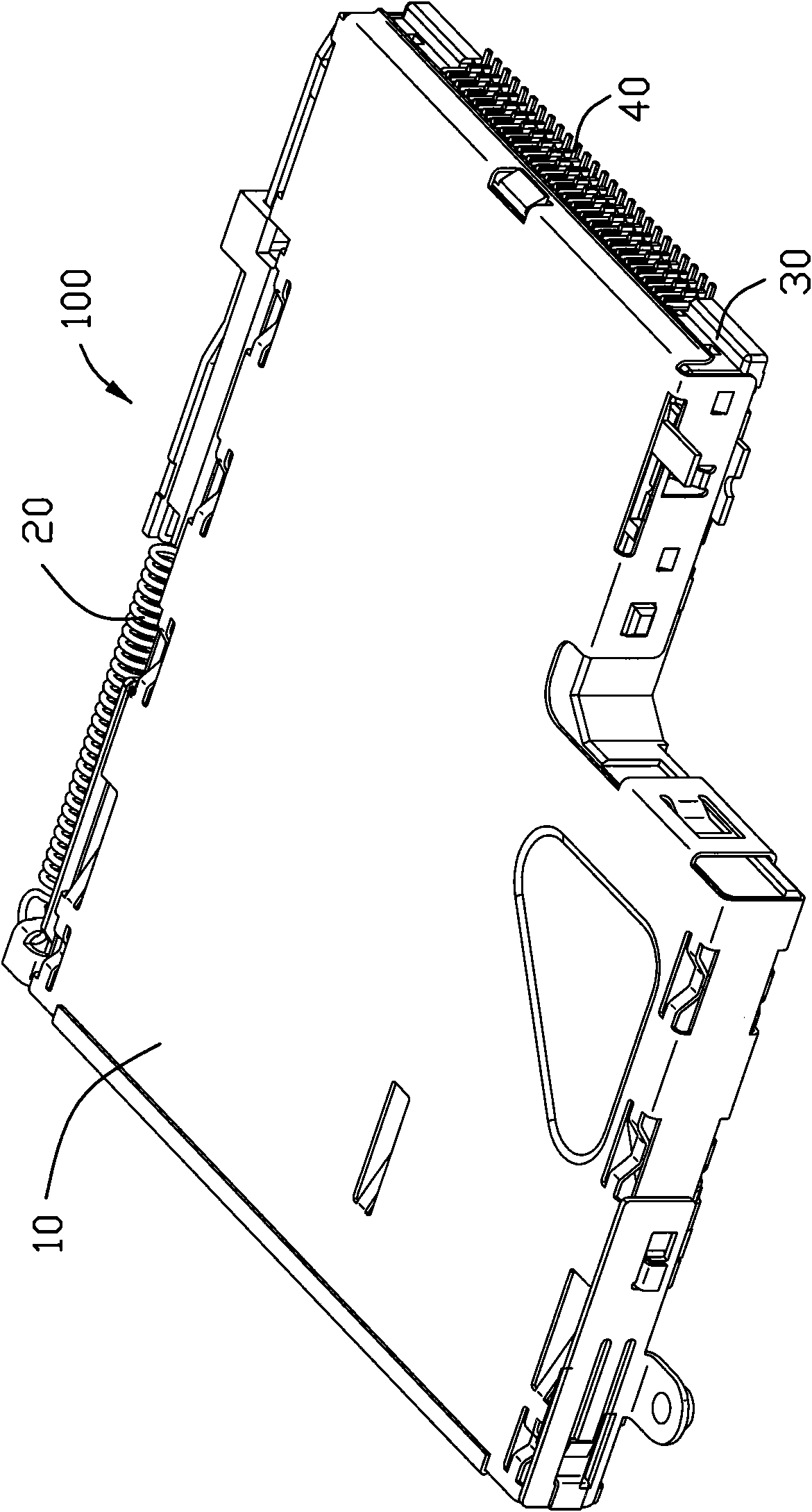
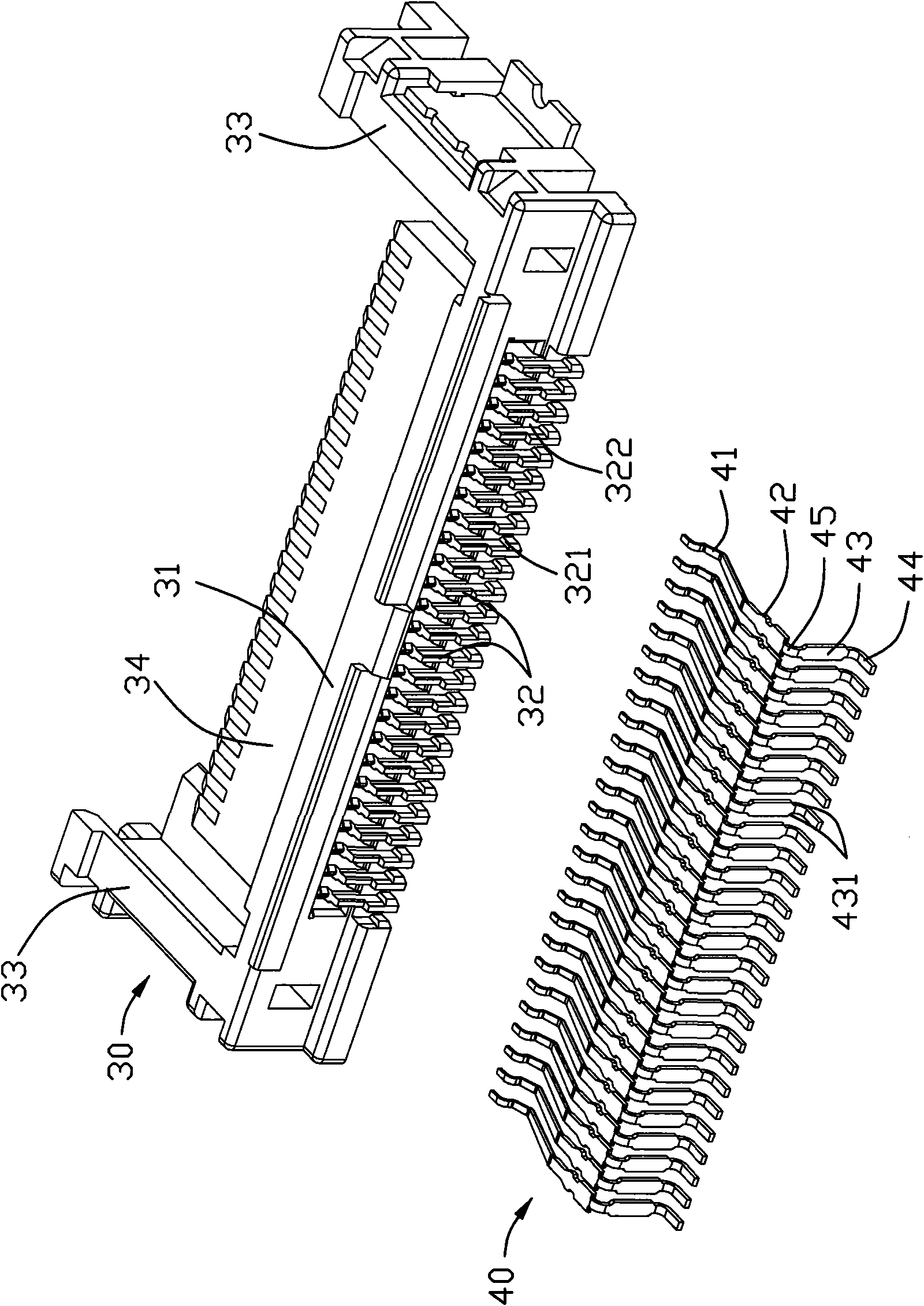
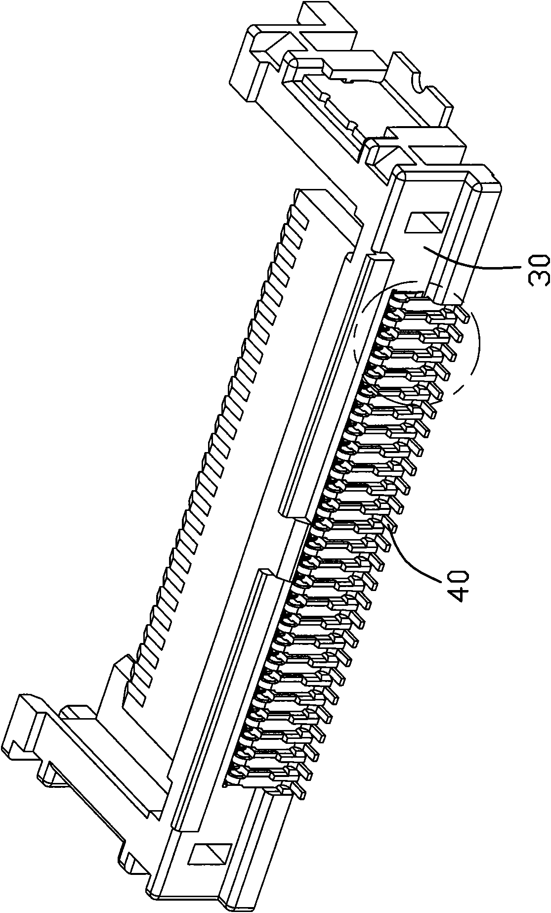
[0012] Below, will combine Figure 1 to Figure 4 The specific implementation manner of the electronic card connector of the present invention is introduced in detail. The electronic card connector 100 of the present invention includes an insulating body 30 , a conductive terminal 40 accommodated in the insulating body 30 , a shielding case 10 , and a card ejecting mechanism 20 mounted on one side of the shielding case 10 . The insulating body 30 is accommodated and installed at the lower part of the front end of the shielding housing 10, thereby forming a storage space (not labeled) surrounded by the insulating body 30 and the shielding housing 10 to accommodate electronic cards. The card ejection mechanism 20 is installed on One side of the housing 10 is shielded to complete the function of inserting and withdrawing the electronic card.

[0013] see figure 2 and Figure 4 As shown, the insulating body 30 includes a base 31, a guide arm 33 extending from both ends of the b...


PUM


Abstract

The invention discloses an electronic card connector, which comprises an insulation body, a shielding shell, a card ejecting mechanism and a plurality of conductive terminals, wherein the front end face of the insulation body is provided with a plurality of fixing arms; the shielding shell shields the insulation body and forms an accommodating space for accommodating an electronic card with the insulation body; the front end face of the insulation body is provided with the plurality of fixing arms, the conductive terminals are accommodated in the insulation body and comprise clipped parts, fixed parts bent downward from the clipping parts and welded parts formed at the end of the fixed parts; the fixed parts of the conductive terminals are wider than the welded parts; and each fixed part is fixedly held between two fixing arms. The structural design can immobilize the conductive terminals and improve product yield.

Description

【Technical field】 [0001] The invention relates to an electronic card connector, in particular to an electronic card connector with a terminal protection structure. 【Background technique】 [0002] With the development of communication and digital electronic technology, there are more and more requirements for the functions of related devices, the capacity of required storage data and the miniaturization of electronic components. Especially under the requirements of miniaturization of electronic components, how to ensure the stability and performance of electronic components and It is particularly important to improve product production yield. [0003] Common electronic card connectors, such as Express card connectors, although a fixed structure is provided at the connection end where the conductive terminals are connected to the printed circuit board, the fixed structure is only a series of barrier blocks between the conductive terminals, and only for mutual protection betwee...

Claims


Application Information

Patent Timeline
Patent Type & Authority Applications(China)
IPC IPC(8): H01R12/16H01R12/32H01R13/40H01R13/46H01R12/55
Inventor 丁建仁郭明伦
Owner FOXCONN (KUNSHAN) COMPUTER CONNECTOR CO LTD
Why Eureka
Try Eureka