[0003]With regard to this, it is the object of the invention to provide a pump assembly which permits a simpler design of the housing parts.
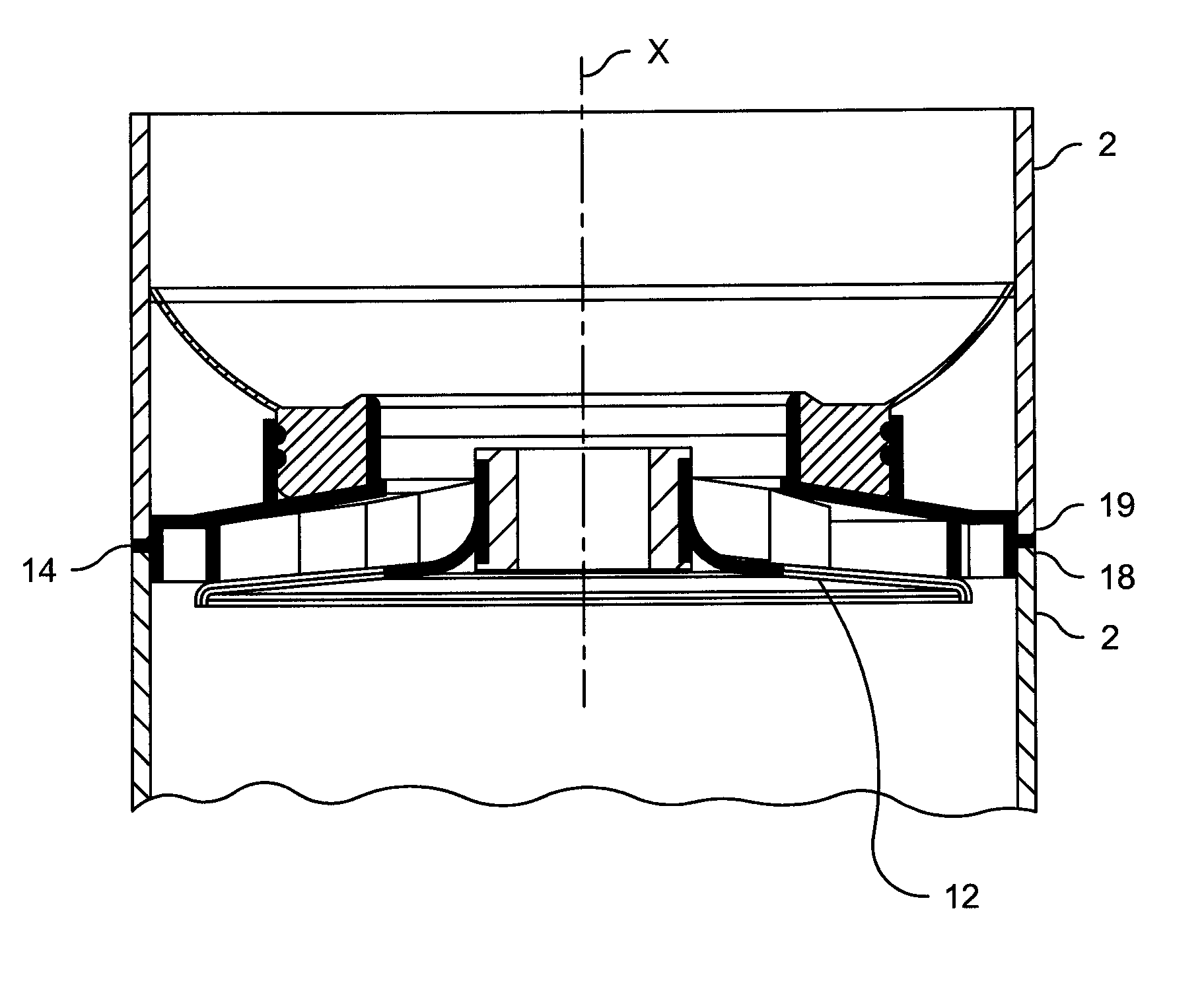
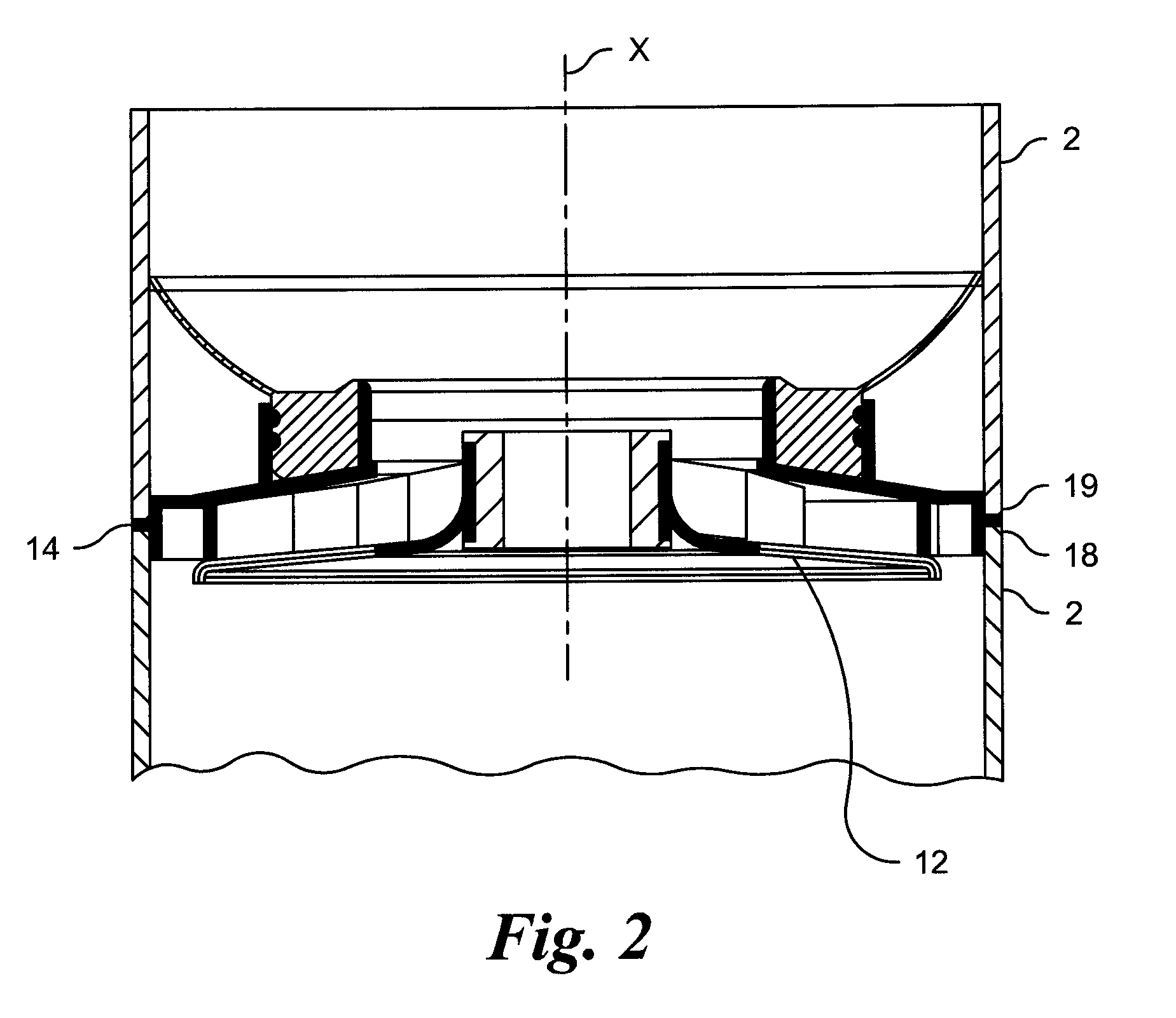
[0006]With the pump assembly according to the invention, a diffuser is fixed in each case between two metallic housing parts, in particular clamped. An axial fixation of the diffuser in the housing may be achieved in a very simple manner by way of this, without additional assembly steps or fastening means being required for the fixation of the diffuser in the housing.
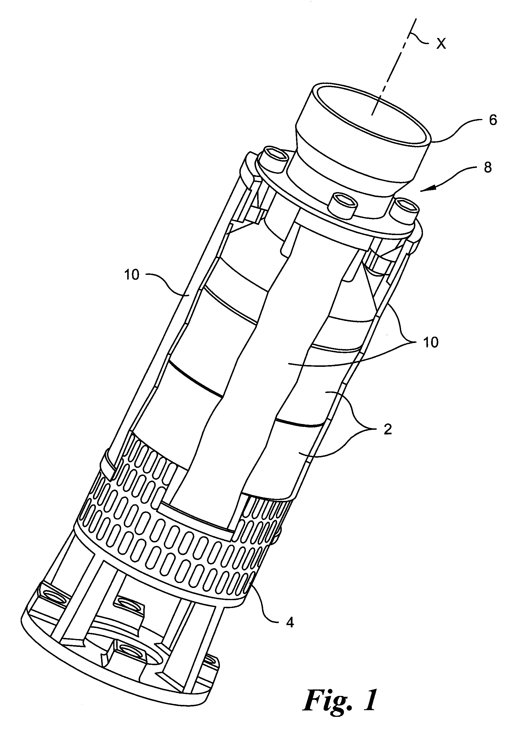
[0007]In order now to be able to design the bearing surfaces on the housing parts in a smaller manner, or to be able to completely make do without these bearing surfaces on the axial ends of the housing parts, according to the invention, it is suggested to connect the two housing parts to one another with a metallic contact in a direct or indirect manner. Thus the force flux of the pressure force in the axial direction, which is transmitted from one housing part onto the adjacent, other housing part, may be effected essentially only via elements of metal. Large bearing surfaces which are necessary when plastic parts are situated in the force flux, may be done away with by way of this design. The metallic elements may accommodate significantly higher pressure / compressive forces than plastic parts, so that here one may allow greater surface pressings, so that the same forces may be transmitted via smaller bearing surfaces. Thus in the ideal case, the housing parts are designed as tube sections, which have a continuous constant inner diameter and outer diameter without broadened bearing surfaces at the axial end. It is thus possible to manufacture these sections in an inexpensive manner without great manufacturing expense either by way of bending sheet metal with a subsequent welding, or by way of cutting a tube / pipe to length. Despite this, a simple fixation of the diffuser between the two housing parts is retained.
[0012]According to a further embodiment of the invention, the diffuser may comprise at least one metallic element, which is clamped between the axial ends of the housing parts. This design thus permits the force flux not having to be effected directly from one housing part onto the next housing part, but indirectly via the metallic element lying therebetween. However, the housing parts remain in metallic contact with one another, i.e. of two housing parts which are adjacent one another, the first housing part bears on one side of the metallic element, whilst the second housing part bears on the opposite side of the metallic element. Thus the force flux may be effected in the axial direction via the metallic elements which may accommodate larger compressive forces than a plastic, from which the remaining diffuser is preferably manufactured. Preferably, the complete force flux in the axial direction which arises on clamping the housing parts, is effected via one or more metallic elements. Thereby however, it is also conceivable for the housing parts to additionally be in direct contact with one another. For this, a projection of the diffuser for example, which engages into a recess of one or both housing parts, may comprise a metallic element or be formed completely of a metallic element.
[0014]Particularly preferably, the metallic element is designed as a metal ring, which projects radially outwards from the outer periphery of the diffuser. Thereby, the metal ring extends so far outwards in the radial direction, that it may come to lie between the housing parts which are adjacent one another. The metal ring extends inwards preferably radially beyond the inner periphery of the housing parts, so that there it may engage into the plastic of the diffuser, i.e. be cast into the diffuser. On the one hand, one may provide a maximum bearing surface for the adjacent housing parts and on the other hand one may achieve a smooth contour on the outer side of the housing, in a very simple manner, due to such a metal ring which is preferably designed in a closed manner and extends over the complete periphery of the diffuser. Preferably, the outer diameter of the metal ring corresponds to the outer diameter of the adjacent housing parts, so that a smooth gapless outer contour of the pump housing may be created when the individual elements are applied onto one another. This embodiment permits a very simple manufacture of the individual housing parts, since these may be designed in a completely tubular manner with smooth end-edges or end-sides. The end-sides, as the case may be, need merely to be turned or ground in a plane manner, and despite this no recesses or grooves are to be machined.
[0015]According to a further embodiment of the invention, the diffuser may be manufactured at least partly of metal and comprise a radially projecting projection, which is clamped between the axial ends of the housing parts. This design too then permits a force transmission in the axial direction only via metallic elements. In particular, it is preferable to design the diffuser as a cast part, for example as a metal powder injection moulded part. Complex shapes may be designed with metal powder injection moulding in a very simple manner. Thus, a radial outwardly projecting projection or several radially outwardly projecting projections may be formed on the diffuser in a simple manner, for the axial fixation of the diffuser. These, since they are designed of metal, may transmit the occurring compressive forces without any problem. However, such metallic projections do not necessarily have to lie in the force flux, but as described above, may also engage into recesses or for example a peripheral groove, which results from the conical shape of the axial end of the housing part. Particularly preferably, the complete diffuser is thus manufactured completely of metal. This may be a single-part design, but it is also possible for the diffuser to be composed of several parts, wherein the parts are then preferably welded to one another.

