Synchrotron power cycling apparatus and method of use thereof

a technology of power cycling and synchrotron, which is applied in the direction of beam deviation/focusing, instruments, and therapy, etc., can solve the problems of reduced ability to repair damaged dna, death of patients, and special vulnerability to attack on dna

Inactive Publication Date: 2013-02-19
BALAKIN ANDREY VLADIMIROVICH +1
View PDF280 Cites 38 Cited by
  • Summary
  • Abstract
  • Description
  • Claims
  • Application Information

AI Technical Summary

Problems solved by technology

These particles damage the DNA of cells, ultimately causing their death.
Cancerous cells, because of their high rate of division and their reduced ability to repair damaged DNA, are particularly vulnerable to attack on their DNA.

Method used


Image

  • Synchrotron power cycling apparatus and method of use thereof
  • Synchrotron power cycling apparatus and method of use thereof
  • Synchrotron power cycling apparatus and method of use thereof

Examples


Embodiment Construction

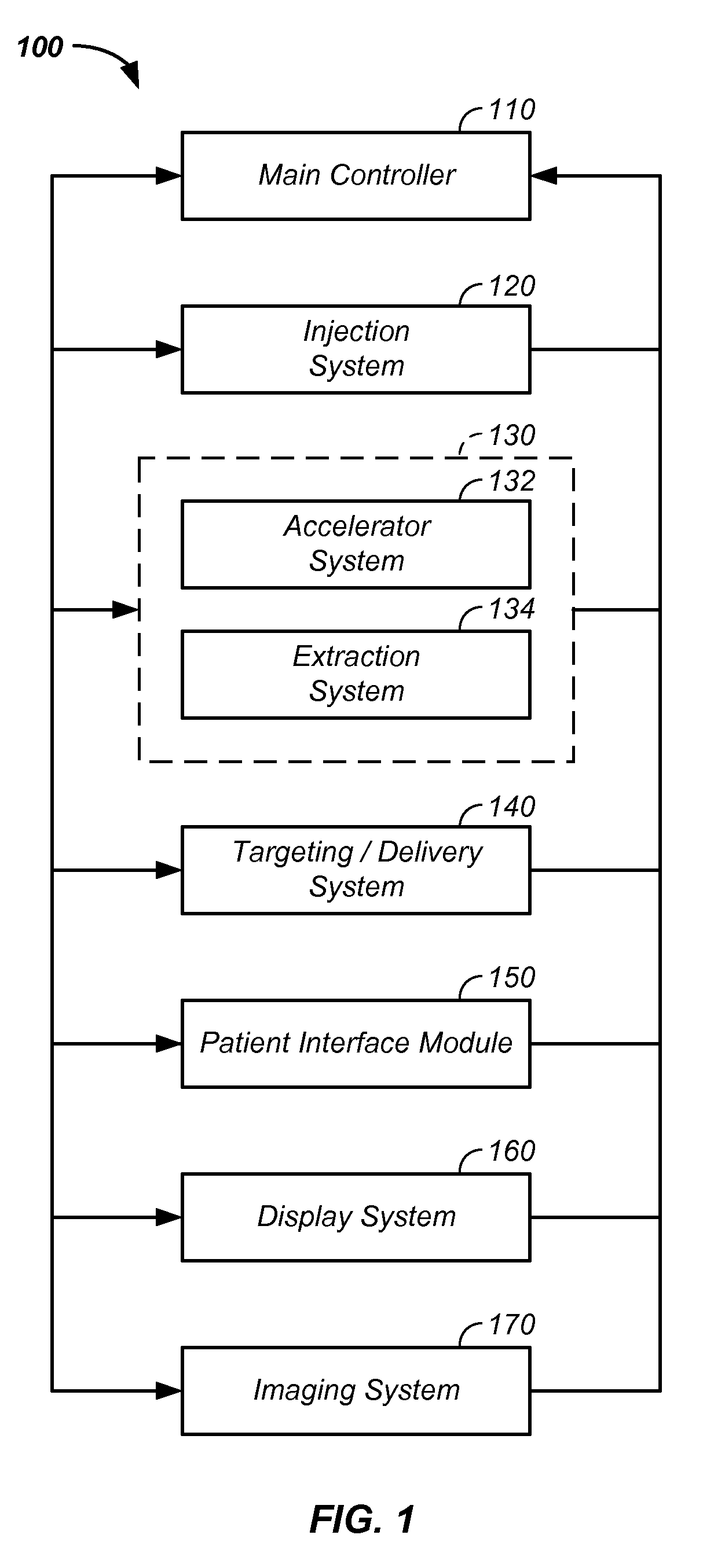
[0105]The invention comprises a method and apparatus to speed recovery time in cycling a charged particle cancer therapy system.

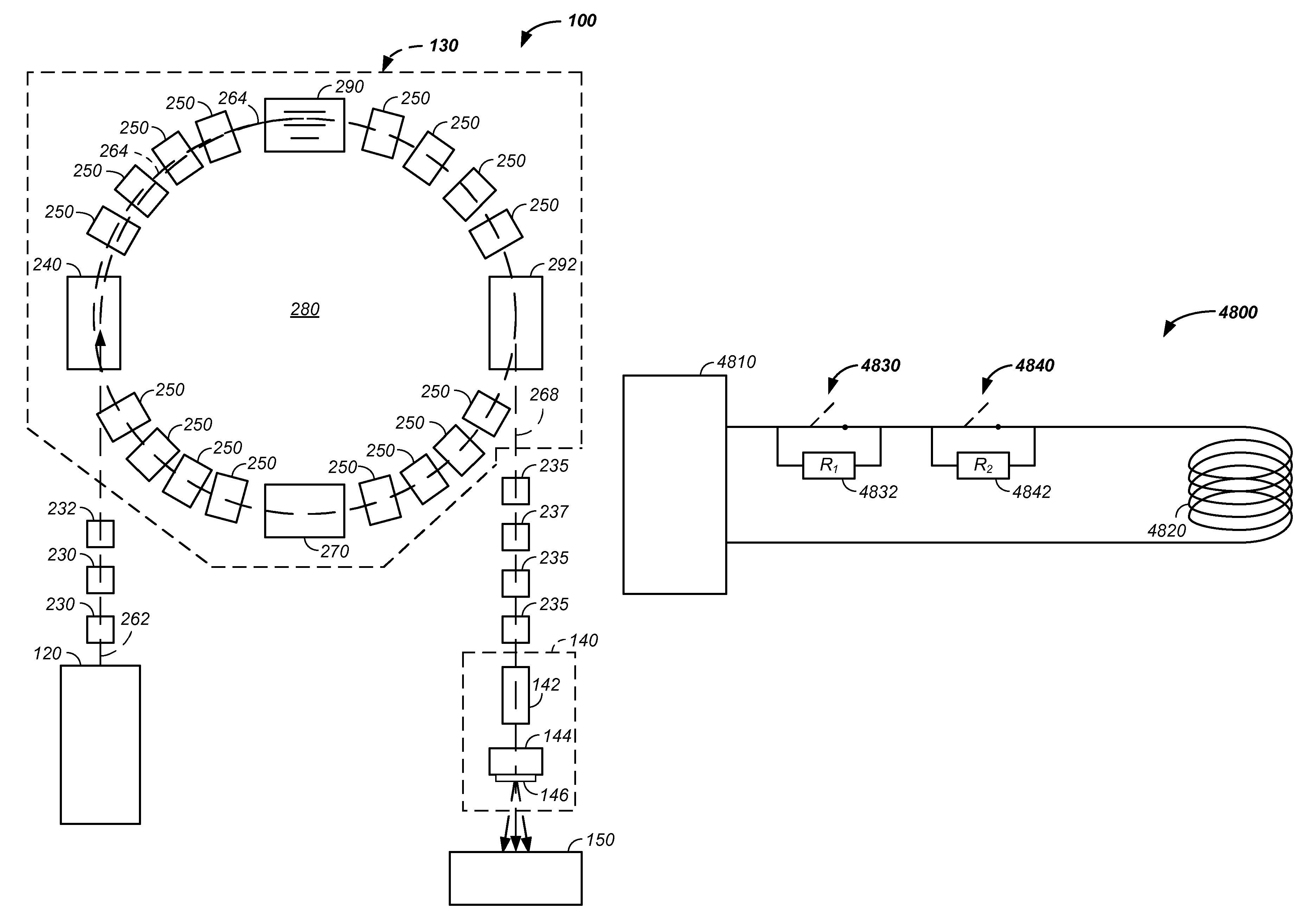
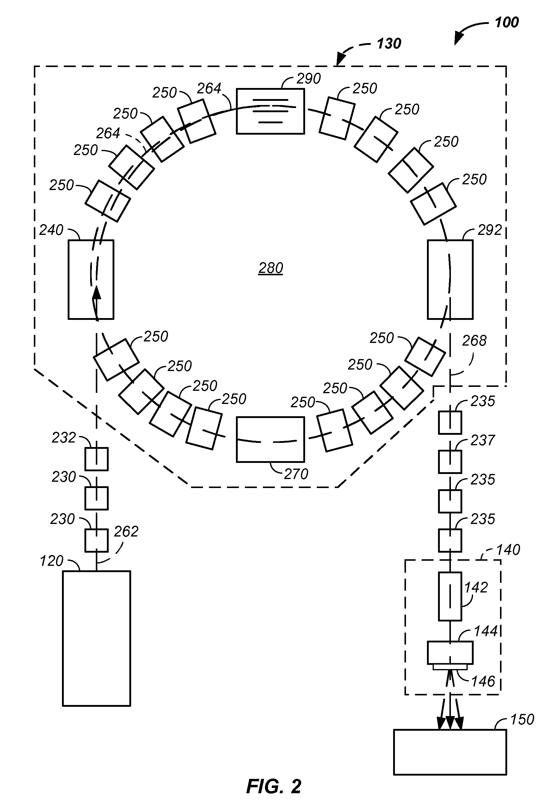
[0106]In one embodiment, one or more switches are used to introduce a corresponding one or more resistors into a circuit linking a power supply to a magnet and / or an inductor during a recovery phase between acceleration cycles of a synchrotron. For example, a charged particle cancer therapy system or synchrotron system uses one or more switches to introduce a corresponding one or more resistors into a circuit linking a power supply to a magnet or an inductor during an applied power recovery phase between acceleration cycles of the synchrotron, which reduces time of reduction in power from an active applied power to a power suitable for use with a subsequent injection of charged particles into the synchrotron.

[0107]Used in combination with the invention, novel design features of a charged particle beam cancer therapy system are described. Particularly, a neg...


PUM


Abstract

The invention comprises a charged particle cancer therapy system or synchrotron system using one or more switches to introduce a corresponding one or more resistors into a circuit linking a power supply to a magnet or an inductor during an applied power recovery phase between acceleration cycles of the synchrotron, which reduces time of reduction in power from an active applied power to a power suitable for use with a subsequent injection of charged particles into the synchrotron.

Description

CROSS-REFERENCES TO RELATED APPLICATIONS[0001]This application:[0002]is a continuation-in-part of U.S. patent application Ser. No. 12 / 425,683 filed Apr. 17, 2009, now U.S. Pat. No. 7,939,809 which claims the benefit of:[0003]U.S. provisional patent application No. 61 / 055,395 filed May 22, 2008, now U.S. Pat. No. 7,939,809 B2;[0004]U.S. provisional patent application No. 61 / 137,574 filed Aug. 1, 2008;[0005]U.S. provisional patent application No. 61 / 192,245 filed Sep. 17, 2008;[0006]U.S. provisional patent application No. 61 / 055,409 filed May 22, 2008;[0007]U.S. provisional patent application No. 61 / 203,308 filed Dec. 22, 2008;[0008]U.S. provisional patent application No. 61 / 188,407 filed Aug. 11, 2008;[0009]U.S. provisional patent application No. 61 / 188,406 filed Aug. 11, 2008;[0010]U.S. provisional patent application No. 61 / 189,815 filed Aug. 25, 2008;[0011]U.S. provisional patent application No. 61 / 201,731 filed Dec. 15, 2008;[0012]U.S. provisional patent application No. 61 / 205,362...

Claims


Application Information

Patent Timeline
Patent Type & Authority Patents(United States)
IPC IPC(8): G21K1/08H05H15/00
CPCA61N5/10H05H7/10H05H13/04A61N2005/1087
Inventor BALAKIN, VLADIMIR
Owner BALAKIN ANDREY VLADIMIROVICH
Why Eureka
Try Eureka