
Flicker detection method and image sensing device utilizing the same

a technology detection method, which is applied in the direction of color signal processing circuit, color television details, television system, etc., can solve the problems that flicker may undermine the performance of image sensing device, and achieve the effect of better image processing

Inactive Publication Date: 2013-02-19
DYNA IMAGE CORPORATION
View PDF7 Cites 45 Cited by
  • Summary
  • Abstract
  • Description
  • Claims
  • Application Information

AI Technical Summary

Benefits of technology

[0009]The method and the device disclosed in the present invention help to filter the flicker from the light signals. So that the image sensing device may get the accurate light information within the images captured by the device, and perform a better image processing based on the accurate light information.

Problems solved by technology

The flicker may undermine the performance of the image sensing devices unless the image sensing devices are equipped with additional components such as frequency identifiers so as to calculate polarities of light intensity via algorithms like Fast Fourier Transform (FFT) before detecting the presence of the flicker.

Method used


Image

  • Flicker detection method and image sensing device utilizing the same
  • Flicker detection method and image sensing device utilizing the same
  • Flicker detection method and image sensing device utilizing the same

Examples


Embodiment Construction

[0021]The aforementioned illustrations and following detailed descriptions are exemplary for the purpose of further explaining the scope of the present invention. Other objectives and advantages related to the present invention will be illustrated in the subsequent descriptions and appended drawings.

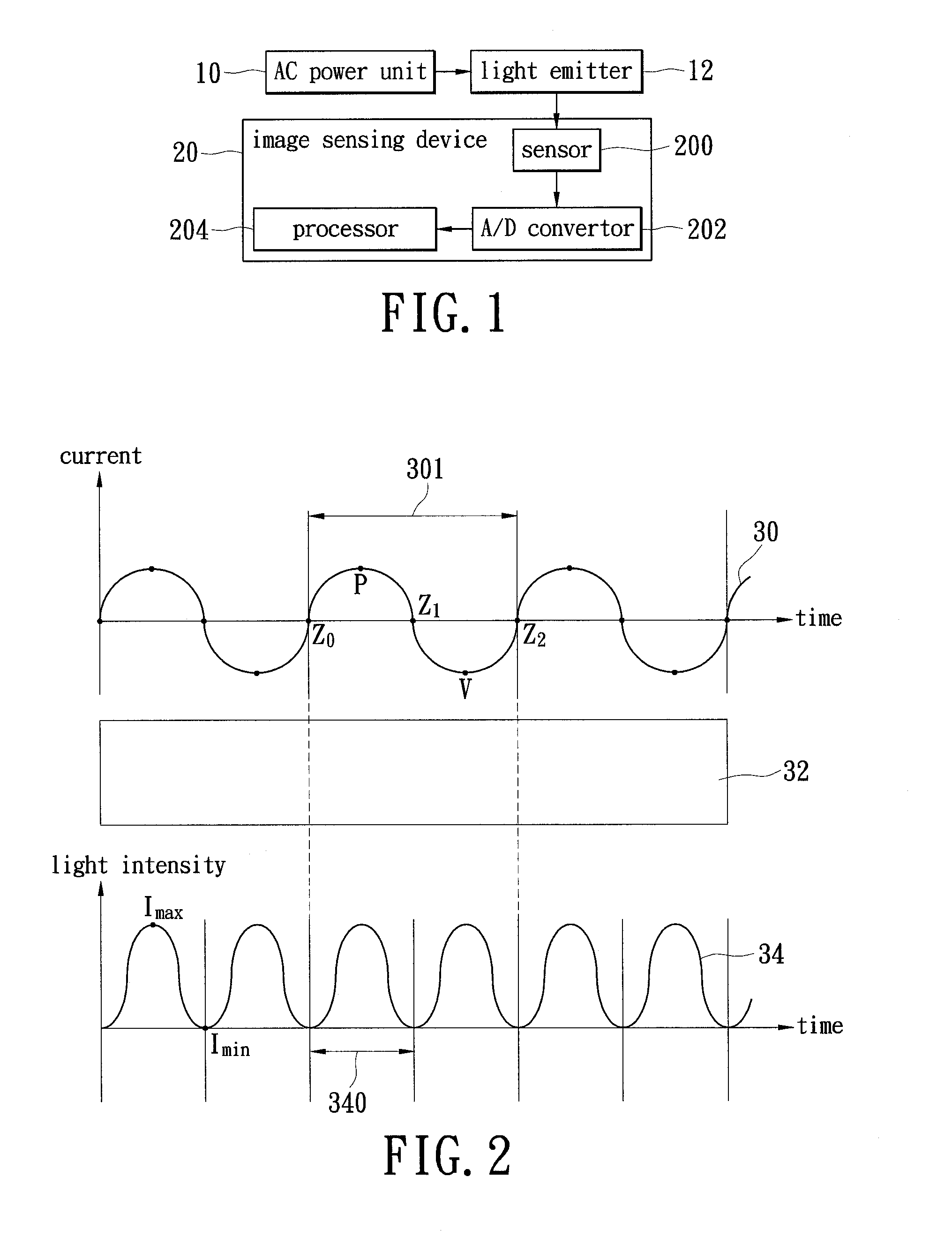
[0022]Please refer to FIG. 1, which shows a block diagram of an image sensing device capable of detecting flicker according to an embodiment of the present invention. The device 20 includes a sensor 200, an (analog to digital) A / D convertor 202, and a processor 204.

[0023]The image sensing device 20 may be located along with a light emitter 12. The light emitter 12 might emit fluorescent light and might be powered by an alternating current (AC) power unit 10. The light that is emitted from the light emitter 12 might periodically switch between “bright” and “dark” as the result of the alternating current provided by the AC power unit 10. Common switch frequencies of the AC power unit 10 ar...


PUM


Abstract

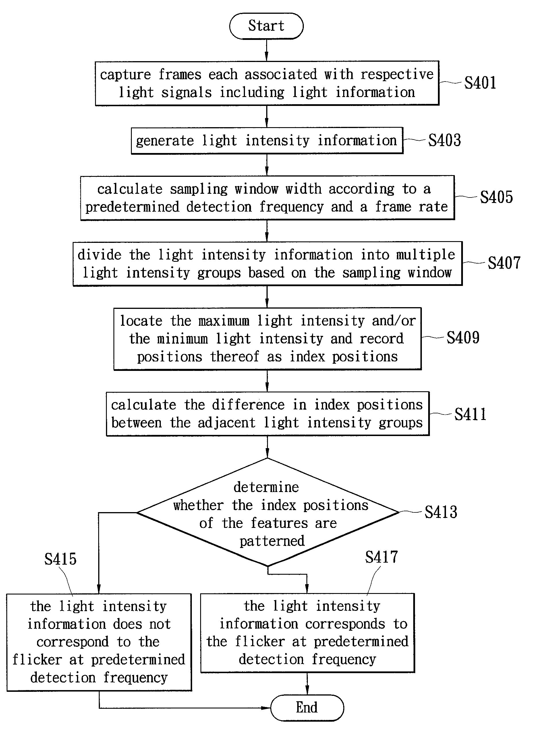
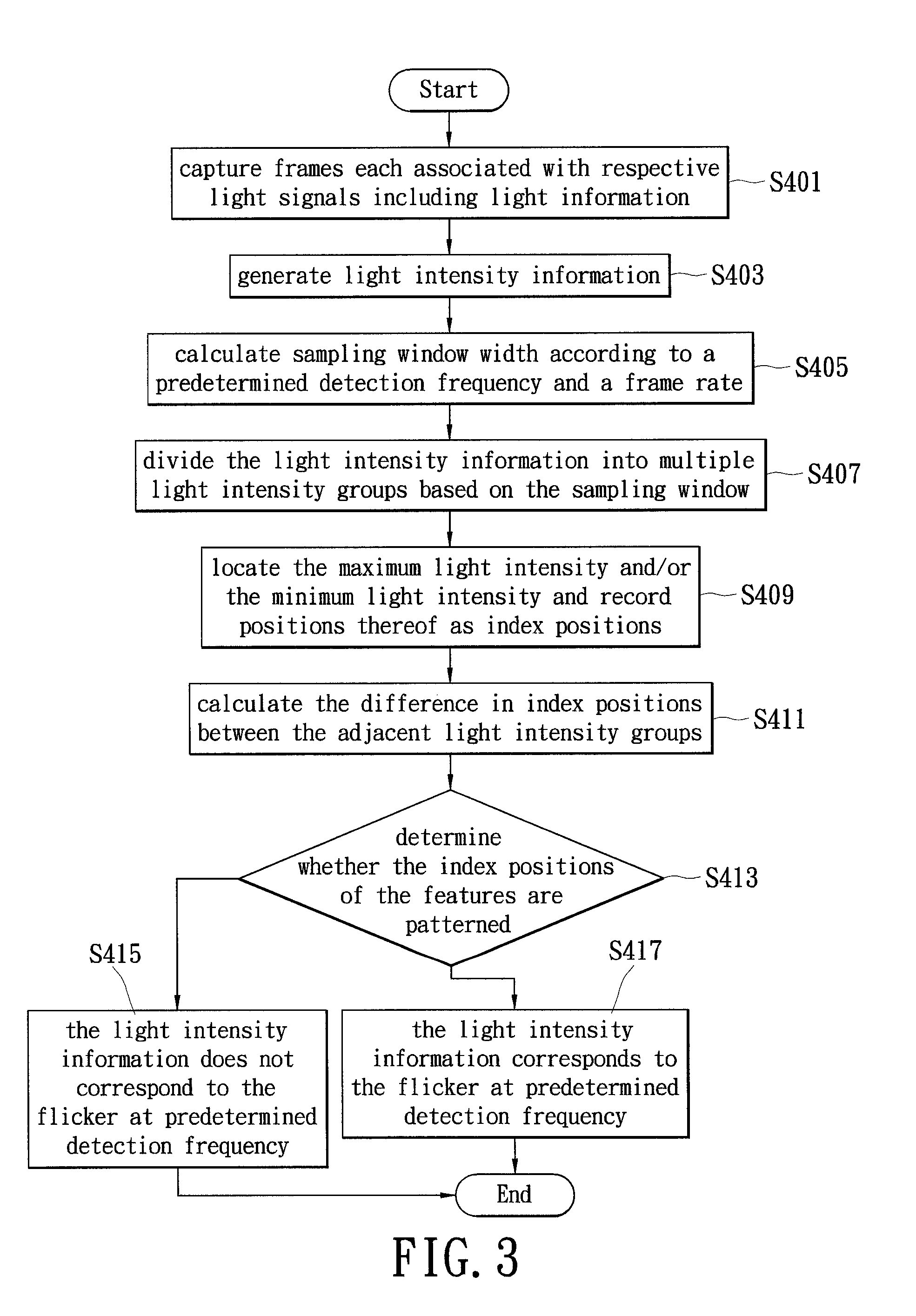
A flicker detection method of an image sensing device is disclosed. The image sensing device includes a sensor and a processor. The method comprises steps of: sequentially detecting multiple frames according to a frame rate, wherein each of the multiple frames includes a light signal; generating a light intensity information based on the light signals; determining a sampling window according to a predetermined detection frequency and the frame rate; dividing the light intensity information into multiple light intensity groups according to the sampling window; distinguishing a feature of each light intensity group, and recording an index position of each feature of the light intensity groups; calculating, individually, a difference between the index positions of the adjacent light intensity groups; and determining whether the differences are patterned, in order to determine whether the light intensity information corresponds to a flicker.

Description

BACKGROUND OF THE INVENTION[0001]1. Field of the Invention[0002]The present invention relates to flicker detection method, and more particularly, to a flicker detection method that is capable of detecting the flicker in the captured images by locating patterns in the difference of the positions of features associated with the flicker.[0003]2. Description of Related Art[0004]Many image sensing devices are configured to detect images and process the captured images based on the brightness of light shown in the images. However, when capturing an image at a frequency that is different to the frequency of switching on / off a light source a “flicker,” which is a periodical light flashing associated with the captured image, may take place.[0005]The flicker may undermine the performance of the image sensing devices unless the image sensing devices are equipped with additional components such as frequency identifiers so as to calculate polarities of light intensity via algorithms like Fast Fo...

Claims


Application Information

Patent Timeline
Patent Type & Authority Patents(United States)
IPC IPC(8): H04N9/73
CPCH04N5/235H04N5/2357H04N23/745H04N23/70
Inventor CHEN, JAU-YU
Owner DYNA IMAGE CORPORATION
Learn More