
Container with suspended rack

a technology of rack and container, which is applied in the direction of baking vessels, containers preventing decay, sealing, etc., can solve the problems of racks 105/b> often not fitting well in the roasting pan, burn and drop injuries to users, and property damage, so as to prevent the movement of the rack within the pan

Active Publication Date: 2013-02-26
LIFETIME BRANDS
View PDF13 Cites 0 Cited by
  • Summary
  • Abstract
  • Description
  • Claims
  • Application Information

AI Technical Summary

Benefits of technology

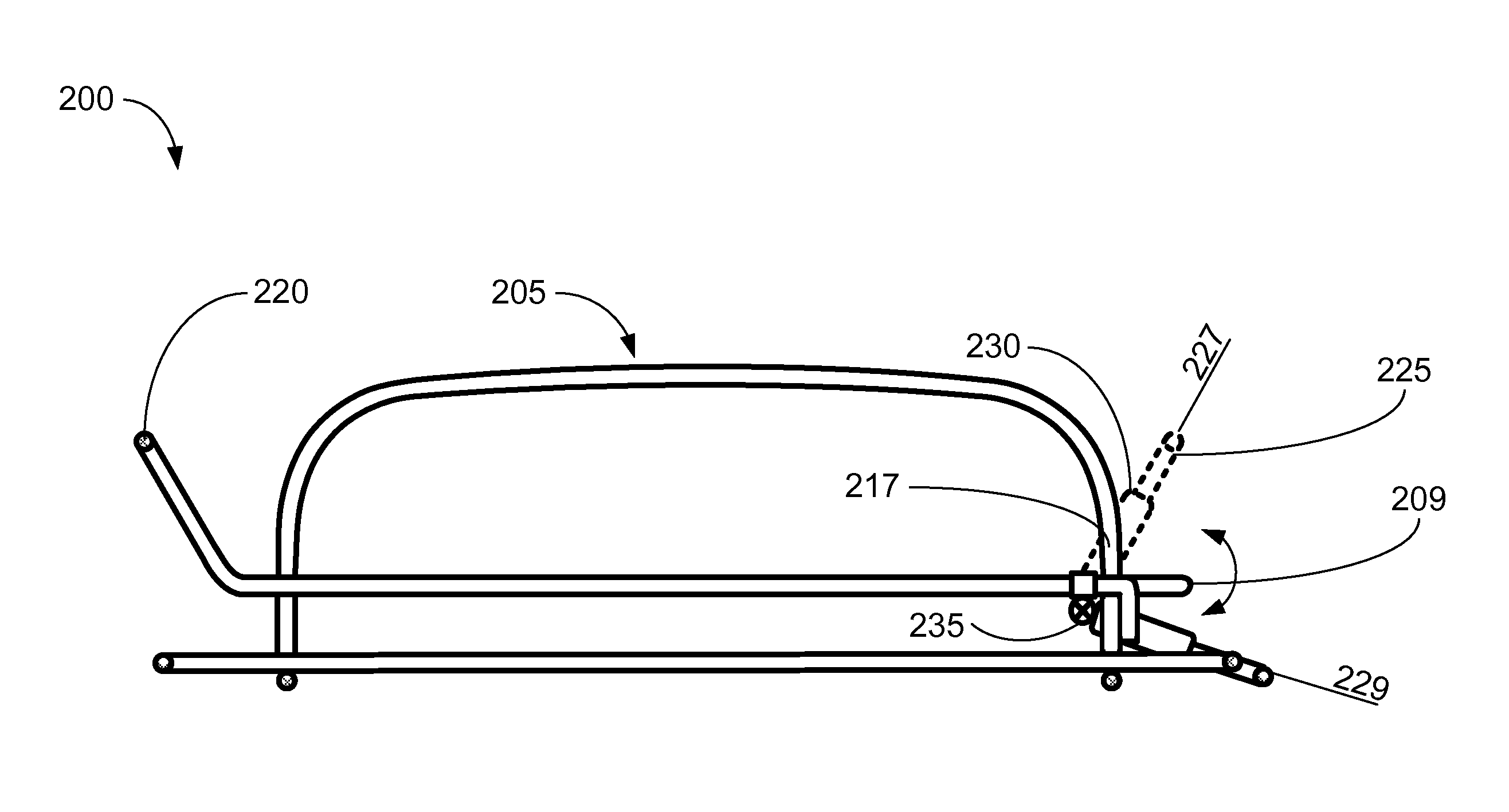
[0016]In some embodiments, the rack can further comprise a gate pivotally coupled to the supporting grid. The gate can have a first, closed position and a second, open position. In the closed position, the gate can contain objects placed on the rack. In the open position, the gate can be rotated down even with, or below, the surface of the supporting grid to enable objects placed on the rack to be removed. The gate can allow objects to be removed from the rack simply by sliding the objects out of the side of the rack. This can preclude the need to lift heavy objects, such as a roast, to remove them from the rack.
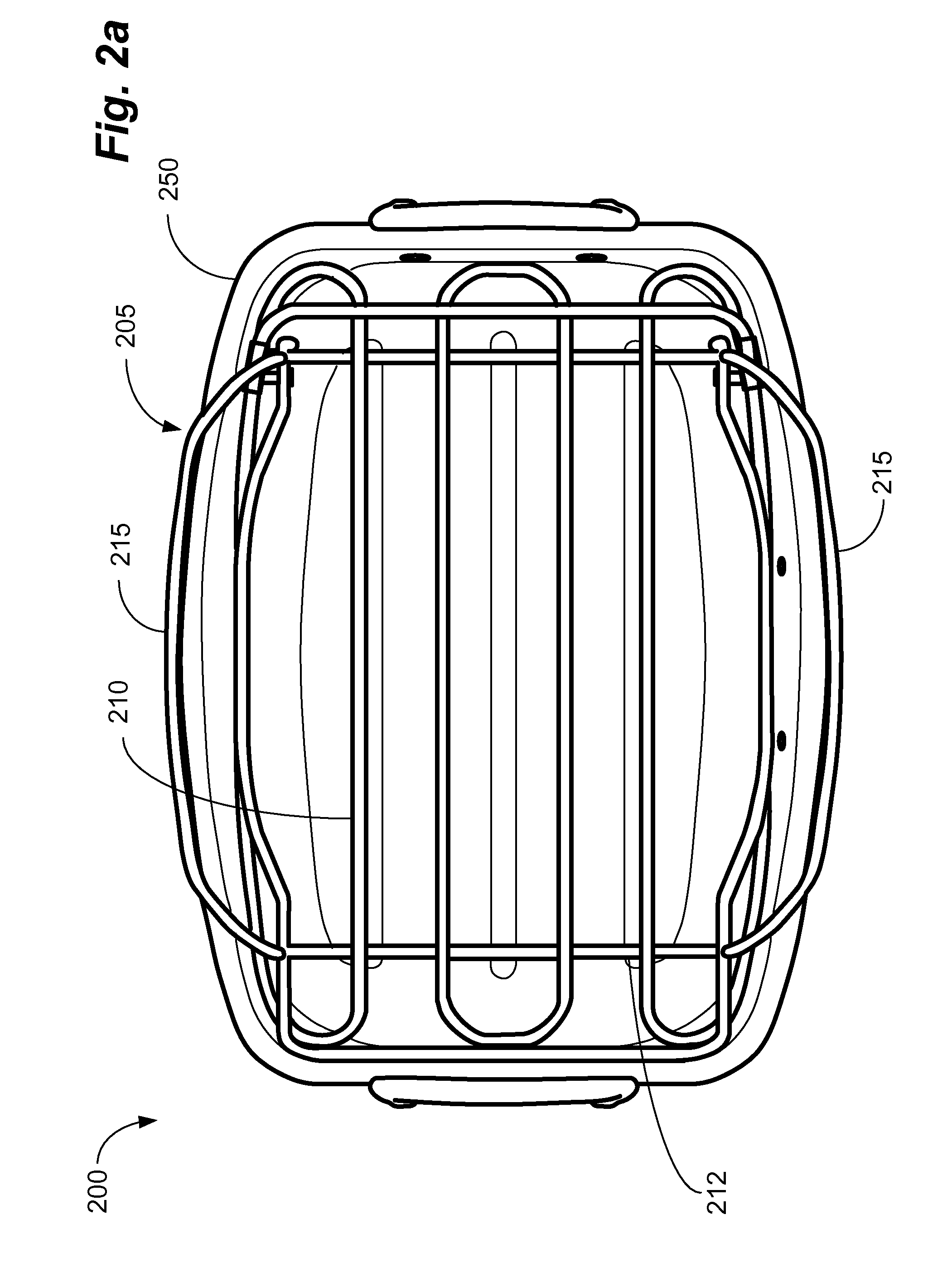
[0018]Embodiments of the present invention also relate to a system comprising the aforementioned rack and a complementary pan. In some embodiments, the pan can have curved sides such that the cross-section of the pan tapers near the bottom. The rack can be sized such that it has substantially the same planform as the tapered portion of the pan. In some embodiments, this can prevent movement of the rack within the pan. In other embodiments, this can hold the rack off the bottom of the pan to hold objects placed thereon above the bottom of the pan. In still other embodiments, the rack can have adjustable feet to vary the height from the bottom of the pan to the rack.
[0019]In some embodiments, the pan can further comprise one or more handles. In some embodiments, the handles can be extended to provide extra room between the pan handles and the pan. This can enable the pan handles to be grasped safely without touching the potentially hot pan. Similarly, in some embodiments, the rack handles can also be extended to provide extra room between the rack handles and the pan, when the rack is installed in the pan. This can enable the rack handles to be grasped safely without touching the potentially hot pan.
[0020]Embodiments of the present invention can further comprise a lid for the pan. The lid can comprise a curved section on a first end and a second end to clear the upright and the gate on the rack. In some embodiments, the lid can further comprise one or more cut-outs to clear the rack handles. In this configuration, the lid can substantially seal the pan despite the protruding upright, gate, and rack handles.

Problems solved by technology

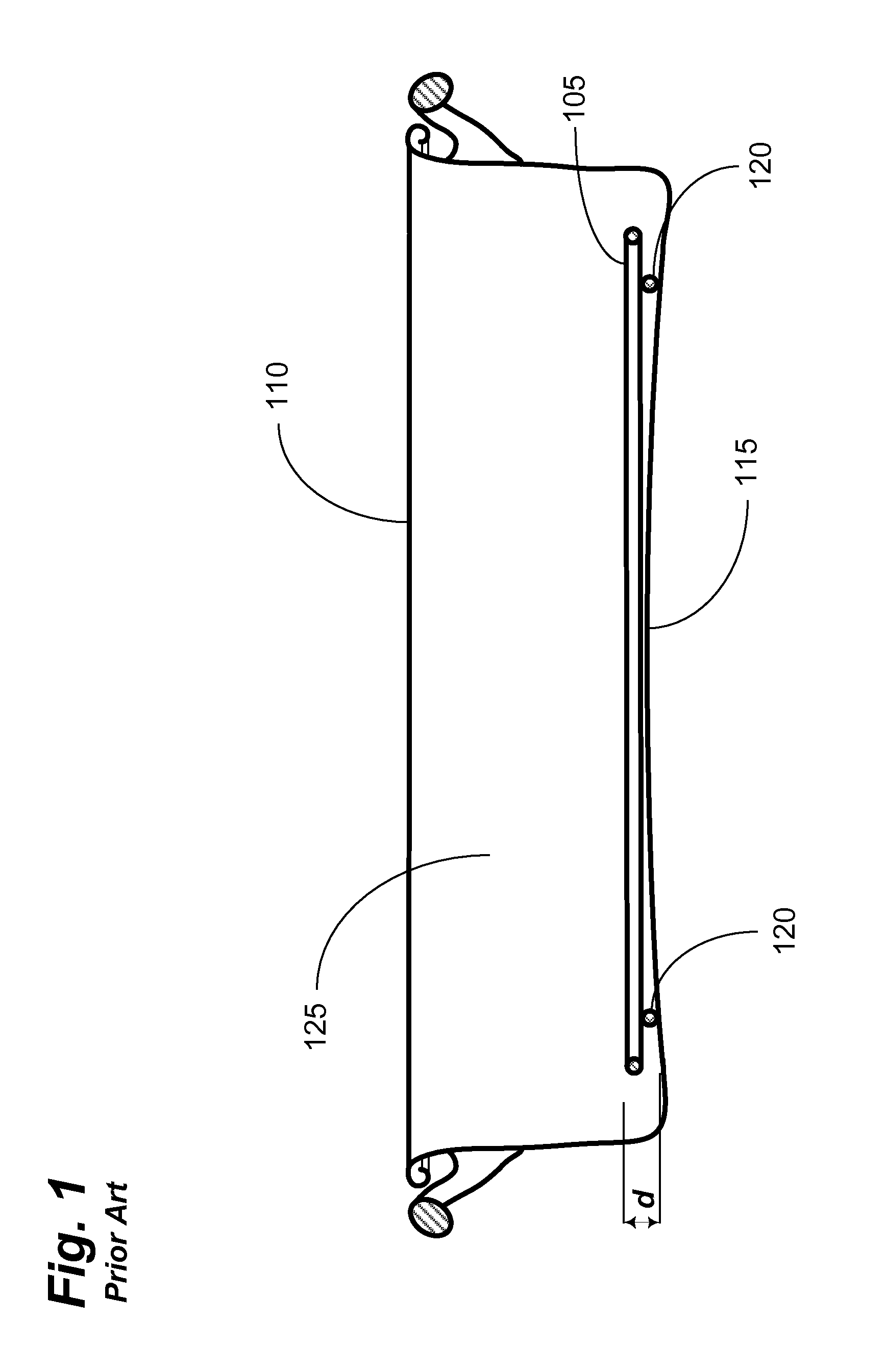
One drawback is that racks 105 often do not fit well in the roasting pan 110 in which they are used.
This can create a problem whereby the user attempts to lift or move the roasting pan 110, e.g., to take the pan out of the oven, and the rack 105 slides within the pan 110.
Given that many roasts weigh more than 20 pounds, this can dramatically change the center of gravity of the pan 110, twisting or tilting the pan, and can lead to several problems.
This can result in both burn and drop injuries to the user, property damage, not to mention loss of the roast.
Given the high cost food and the risk of injury, this can cause significant economic and physical damages.
Another problem associated with conventional racks 105 is that they generally lack handles.
This configuration can present a second significant problem: removing the roast from the roasting pan 110.
This can be very difficult to do, however, given the depth of a typical roasting pan 110 and the temperature at which the pan 110 typically comes out of the oven.
On the other hand, wearing an oven mitt or other protective clothing can make it impossible for the user to fit their hand between the roast and the pan 110.
In either case, removing the roast from the pan 110 is at best awkward and at worst dangerous.
This can make the rack 105 very difficult to grasp with conventional kitchen utensils.
In addition, picking up the rack 105 with the roast thereon may exceed the load carrying capacity of the rack 105 causing it to bend or break.
This can also cause the user to be injured as they drop, or attempt to prevent dropping, the roast.
This can make the bottom of the roast soggy and unappetizing and can increase the fat and cholesterol content of the roast.

Method used


Image

  • Container with suspended rack
  • Container with suspended rack
  • Container with suspended rack

Examples


Embodiment Construction

[0031]To facilitate an understanding of the principles and features of embodiments of the invention, they are explained hereinafter with reference to implementations in illustrative embodiments. Embodiments of the invention are described in the context of being a system comprising a floating rack in a container and in particular, to a floating rack in a roasting pan. The rack can further comprise one or more folding gates to facilitate removal of items placed thereon for use in many cooking applications.

[0032]The materials described hereinafter as making up the various elements of the present invention are intended to be illustrative and not restrictive. Many suitable materials that would perform the same or a similar function as the materials described herein are intended to be embraced within the scope of the invention. Such other materials not described herein can include, but are not limited to, materials that are developed after the time of the development of the invention, for...


PUM


Abstract

A system for providing a cooking rack, with or without a complementary container. The rack can comprise lateral elements and longitudinal elements arranged to form a grid. The rack can comprise a gate that can be affixed in a first position and moved from the first position to a second position. In the second position, items can easily be removed from the rack without lifting the items. The rack can further comprise one or more handles to facilitate movement of the rack by the user. The system can comprise a rack and a complementary pan. The pan can comprise a radiused bottom to enable the rack to sit in the pan above the bottom of the pan. The pan can further comprise one or more handles to facilitate movement of the pan by the user.

Description

CROSS-REFERENCE TO RELATED APPLICATIONS[0001]This application claims the benefit, under 35 U.S.C. §119(e), of U.S. Provisional Application Ser. No. 61 / 161,638, filed 19 Mar. 2009, the entire contents and substance of which is hereby incorporated by reference.BACKGROUND OF THE INVENTION[0002]1. Field of the Invention[0003]The present invention relates generally to a container with a suspended rack, and in particular, to a container with a suspended rack comprising a gate on one or more sides to ease removal of objects placed thereon.[0004]2. Description of the Related Art[0005]Various types of pans and pots with racks exist and are used for a multitude of purposes. For example, household ovens generally have racks built into them. These racks are used to suspend cookware placed in the oven and to enable heat to circulate evenly around the cookware. The racks often slide in and out on tracks provided in the oven to aid in inserting and removing objects to and from the oven. The racks ...

Claims


Application Information

Patent Timeline
Patent Type & Authority Patents(United States)
IPC IPC(8): A47J36/00
CPCA47J36/22
Inventor KRENT, ADAMLAZAROFF, WILLIAM J.
Owner LIFETIME BRANDS
Learn More