
Piezoelectric resonator structure having an interference structure

a piezoelectric resonator and interference structure technology, applied in piezoelectric/electrostrictive/magnetostrictive devices, piezoelectric/electrostriction/magnetostriction machines, electrical equipment, etc., can solve the problem of increasing the dimension of each die, increasing the cost of manufacturing the die, and not necessarily increasing the q/sub>p performance. risk of generating strong ripples in the pass band of a filter

Active Publication Date: 2013-02-26
AVAGO TECH INT SALES PTE LTD
View PDF14 Cites 29 Cited by
  • Summary
  • Abstract
  • Description
  • Claims
  • Application Information

AI Technical Summary

Problems solved by technology

Although the performance may have been improved, the dimension of each die is increased, so does the cost of manufacturing the die.
However, the minimization of the lateral modes does not necessarily mean increased Qp performance because the acoustic energy leaked to outside of the resonator may not be reduced.
The spurious resonances cause a risk of generating strong ripples in the pass band of a filter.
Hence, a heretofore unaddressed need exists in the art to address the aforementioned deficiencies and inadequacies.

Method used


Image

  • Piezoelectric resonator structure having an interference structure
  • Piezoelectric resonator structure having an interference structure
  • Piezoelectric resonator structure having an interference structure

Examples


Embodiment Construction

[0043]The present invention is more particularly described in the following examples that are intended as illustrative only since numerous modifications and variations therein will be apparent to those skilled in the art. Various embodiments of the invention are now described in detail. Referring to the drawings, like numbers indicate like components throughout the views. As used in the description herein and throughout the claims that follow, the meaning of “a”, “an”, and “the” includes plural reference unless the context clearly dictates otherwise. Also, as used in the description herein and throughout the claims that follow, the meaning of “in” includes “in” and “on” unless the context clearly dictates otherwise.

[0044]The terms used in this specification generally have their ordinary meanings in the art, within the context of the invention, and in the specific context where each term is used. Certain terms that are used to describe the invention are discussed below, or elsewhere ...


PUM


Abstract

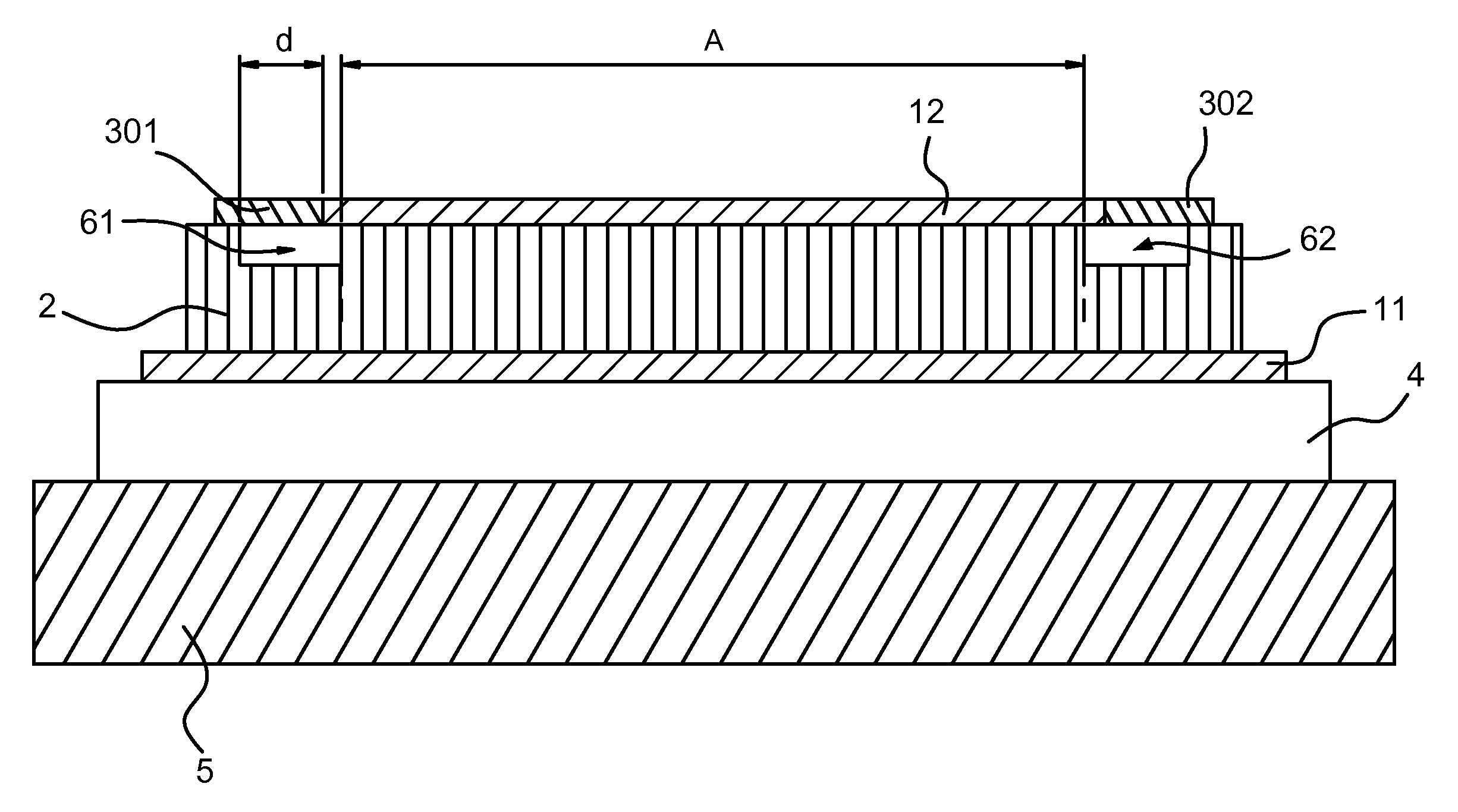
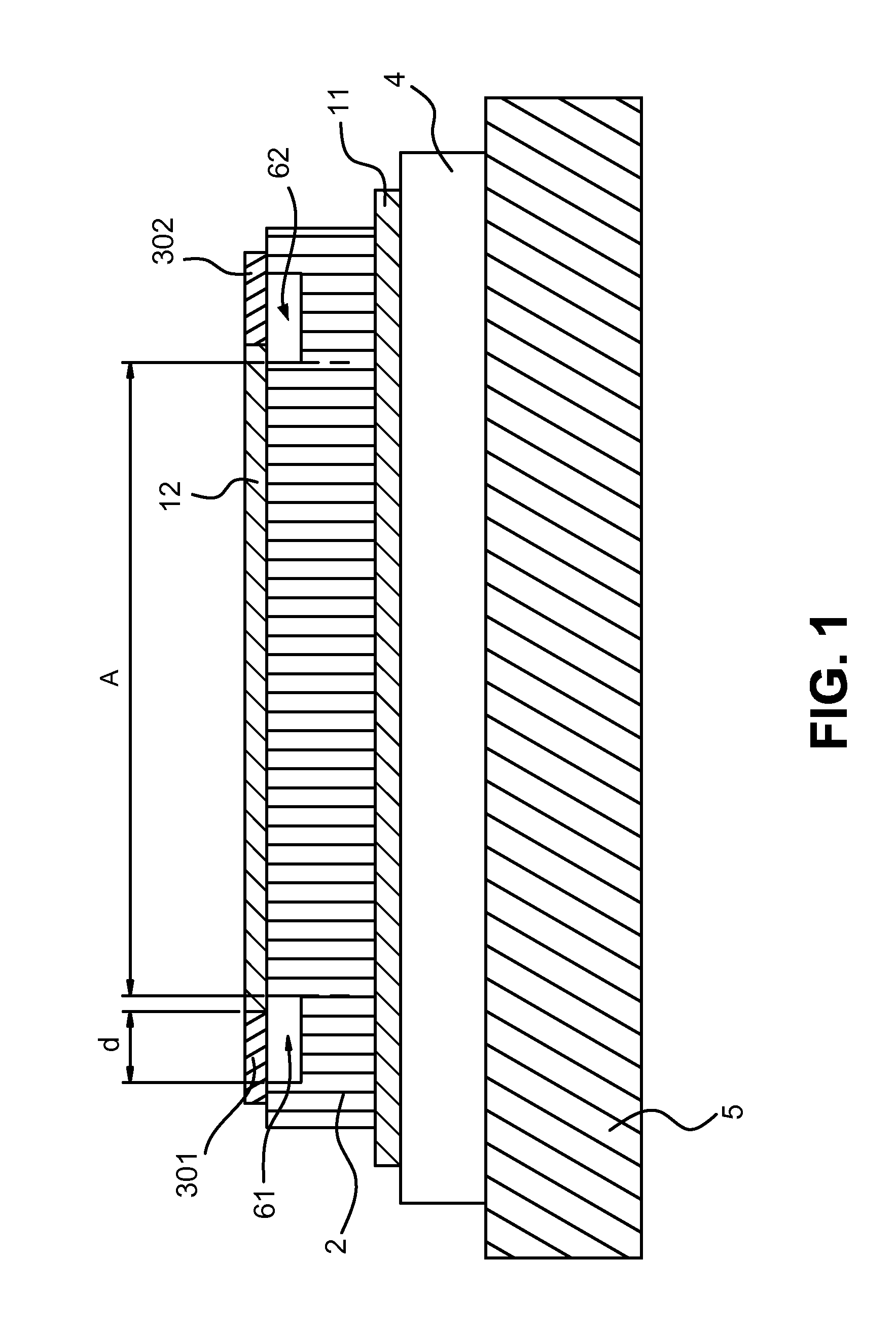
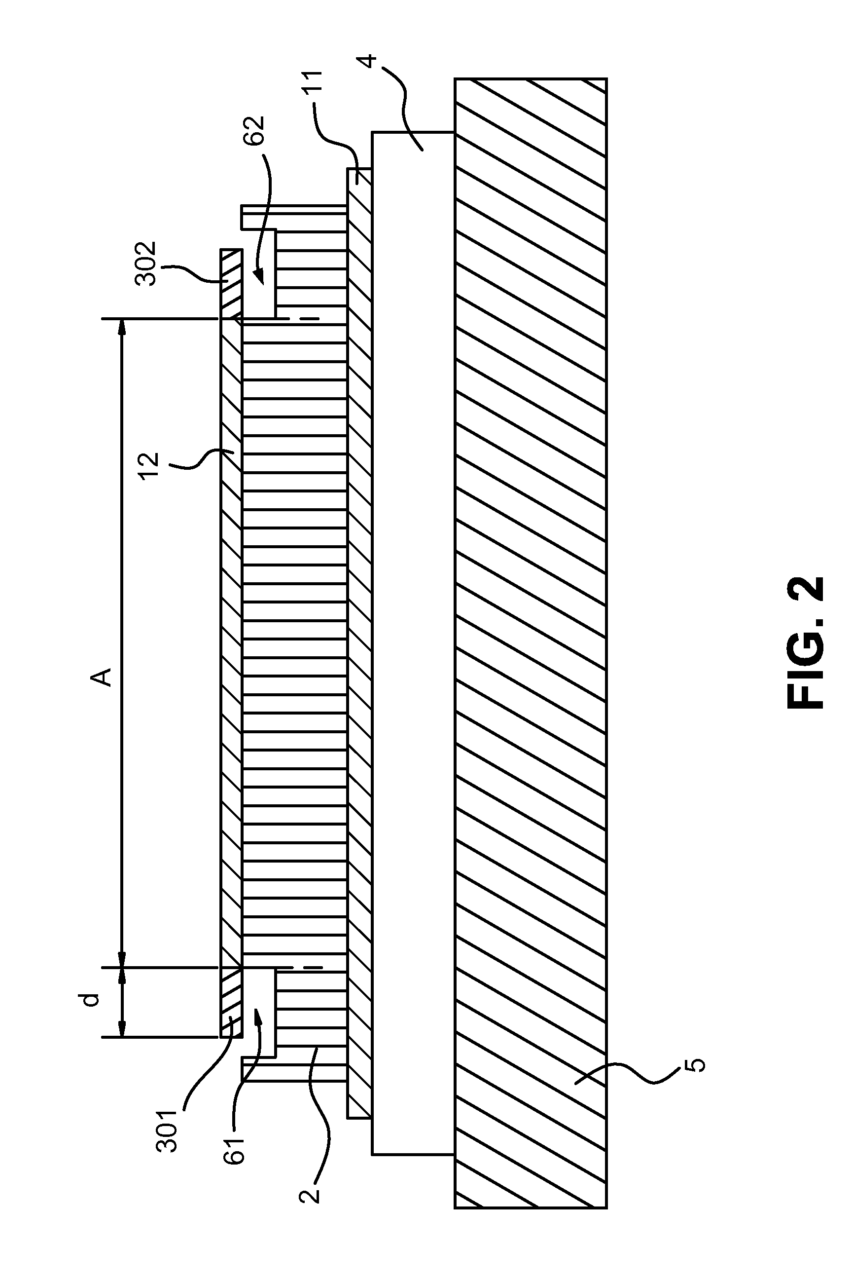
A piezoelectric resonator structure, comprising: (i) a substrate, (ii) an acoustic mirror, (iii) a first electrode, (iv) a piezoelectric layer, and (v) a second electrode, wherein each of the substrate, the acoustic mirror, the first electrode, the piezoelectric layer, and the second electrode has a top surface and a bottom surface, a first end portion and an opposite, second end portion, and a body portion defined therebetween, wherein the overlapped area of body portions of the substrate, the acoustic mirror, the first electrode, the piezoelectric layer and the second electrode is defined as an active area A. A plurality of air gaps and interference structures is formed at the first end portion of the piezoelectric layer and the second electrode, and the second end portion of the piezoelectric layer and the second electrode to enhance the performance of the piezoelectric resonator.

Description

CROSS-REFERENCE TO RELATED PATENT APPLICATION[0001]Some references, which may include patents, patent applications and various publications, are cited and discussed in the description of this invention. The citation and / or discussion of such references is provided merely to clarify the description of the present invention and is not an admission that any such reference is “prior art” to the invention described herein. All references cited and discussed in this specification are incorporated herein by reference in their entireties and to the same extent as if each reference were individually incorporated by reference.FIELD OF THE INVENTION[0002]The present invention relates generally to bulk acoustic wave devices, and more particular to thin film piezoelectric resonator structure having enhanced electrical performance.BACKGROUND OF THE INVENTION[0003]Piezoelectric bulk acoustic wave resonators employed in radio-frequency (RF) filters for wireless communication equipments are generall...

Claims


Application Information

Patent Timeline
Patent Type & Authority Patents(United States)
IPC IPC(8): H03H9/15H03H9/54H03H9/13
CPCH03H9/02118H03H9/175
Inventor ZHANG, HAO
Owner AVAGO TECH INT SALES PTE LTD
Learn More