Ultrasound transducers for imaging and therapy

a transducer and ultrasound technology, applied in the field of ultrasound for imaging and therapeutic purposes, can solve the problems of difficult to meet the desire for high efficiency during ultrasound therapy, difficult to meet the desire for broad bandwidth during ultrasound imaging, and the same transducer design, so as to improve the likelihood, improve the bonding strength, and widen the imaging and treatment field

Inactive Publication Date: 2006-06-20
OTSUKA MEDICAL DEVICES
View PDF84 Cites 298 Cited by
  • Summary
  • Abstract
  • Description
  • Claims
  • Application Information

AI Technical Summary

Benefits of technology

[0017]The present invention provides an ultrasound transducer apparatus comprising a generally concave array of ultrasound transducer elements. The apparatus enables a reduced number of transducer elements and a larger pitch size compared to that used for the elements in a traditional linear array of transducer elements. Reducing the number of elements also reduces the required number of connection cables and control channels. While providing the same performance, the concave array system is much simpler and less costly than a conventional linear phased array system. The concave geometry also requires smaller phase differences between transducer elements, thus reducing cross-talk and heating in kerf fills between elements. The geometry also reduces the affect of grating lobe problems during the beam-forming process.
[0019]To control a location of a focus point of the transducer array, one form of the invention includes a beam steering mechanism, or controller, to adjust the phases or the delays of signals that drive the transducer elements. To increase the transducer bandwidth for better image resolution, an electrical damping circuit can be included to provide the equivalent of a mechanical backing. One or more material acoustic matching layers and / or air backing can optionally be included to improve the transducer efficiency and bandwidth. In addition, the present invention may optionally include one or more metal matching layers to improve heat dissipation by the transducer.
[0020]A flexible transducer array is preferably provided to control the location of the focus point. Flexible outer layers and kerf fills between transducer elements enable the array to bend in different curvatures. As with a fixed curvature array, the flexible array reduces the number of required transducer elements. However, the flexible array embodiment also enables a practitioner to adjust the imaging field of view (FOV) and simplifies control of the treatment focusing, by changing the geometric shape of the array.
[0022]Another embodiment of the invention includes a plurality of transducer arrays, each directed toward a common focus point. Using multiple transducer arrays enables each array to contain fewer transducer elements and provides a relatively wide imaging and treatment field. Each transducer array may also be allowed to pivot about a pivot point, such that controlled pivoting of the multiple transducer arrays controls the location of the common focus point. This enables controlled movement of the common focus point in at least two directions.
[0023]Another aspect of the invention includes a transducer manufacturing method to produce an ultrasound transducer apparatus with a generally concave geometry. The method comprises the step of providing kerf fills having a non-uniform stiffness to control the curvature of the transducer array. For example, providing kerf fills with a symmetrically non-uniform stiffness improves the likelihood of obtaining a symmetric semi-circle shape of the array, rather than a parabolic shape, when moving one end of a transducer array, compared to an array that has uniformly stiff kerf fills. Alternatively, or in addition, the method may include the step of providing support layers having a non-uniform stiffness. Another step of the method preferably includes cutting grooves into a metal support layer between the transducer elements on the side of the support layer that supports the transducer elements to avoid bonding between the transducer element and the metal support layer. Further steps optionally include cutting grooves into an opposite side of the support layer, and casting an outer matching layer over the support layer and into the grooves to improve the bonding strength between the support layer and an outer matching layer. If the outer matching layers, or support layers, are not deformable, alternate steps to provide flexibility include cutting the outer matching layer into thin strips after bonding the outer matching layer to the support layer, and then filling the kerfs with deformable material.

Problems solved by technology

High intensity focused ultrasound, which can have an intensity above 1000 watts per square centimeter, can raise the tissue temperature at the region of the spatial focus to above 60 degrees Celsius in a few seconds and can cause tissue necrosis almost instantaneously.
Often, however, the desire for high efficiency during ultrasound therapy and the desire for broad bandwidth during ultrasound imaging are difficult to satisfy simultaneously in the same transducer design.
The disadvantage of the electronic device is its complexity and associated relatively high cost.
However, system and transducer complexity is still one of the major disadvantages of electronic therapeutic arrays.
The thick cable required to meet this need makes the device difficult to handle.
Considering all these constraints, it will be evident that the complexity of such a therapeutic phased array, including the cable and the control system coupled to it, can easily become impractical to engineer, and its cost will most certainly exceed the budget of most medical facilities.
It is for these reasons that the therapeutic phased array has not been widely accepted.
For example, in many endoscopic, therapeutic-ultrasound applications, there are limitations on the size of the treatment devices that can be employed.
Oftentimes, however, it is difficult to register the two planes from two spaced-apart transducers.
Sometimes, there are blind spots in the treatment zone, which are not observable in the imaging plane.
The prior art has not dealt extensively with the problem of designing a dual-purpose phased array transducer.
Besides the conflict between the disparate design parameters that must be satisfied to achieve efficiency and adequate bandwidth in such a transducer, as noted above, there are other unresolved issues in making a therapeutic phased array transducer, such as heat dissipation, and element cross-talk.

Method used


Image

  • Ultrasound transducers for imaging and therapy
  • Ultrasound transducers for imaging and therapy
  • Ultrasound transducers for imaging and therapy

Examples


Embodiment Construction

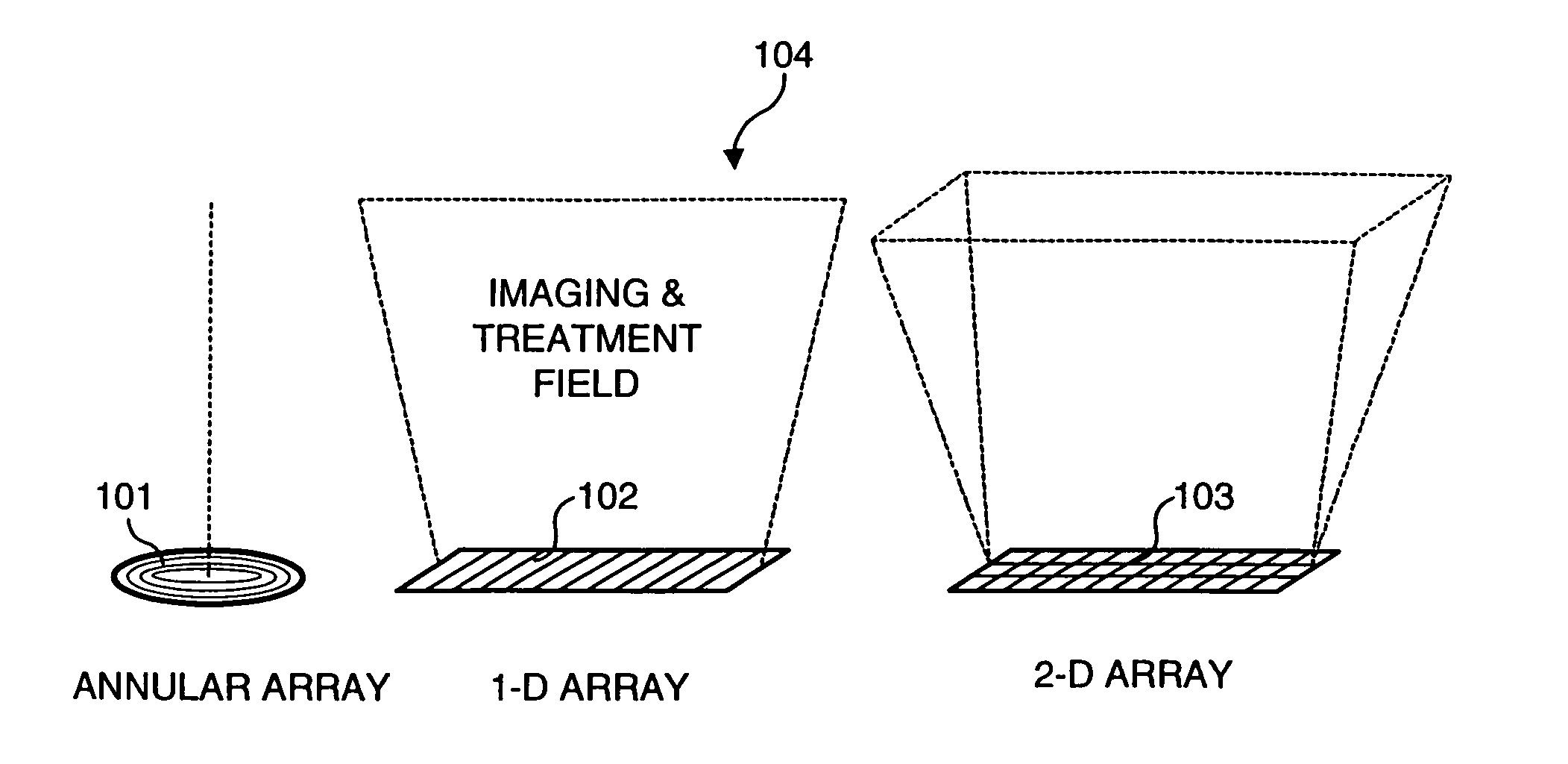
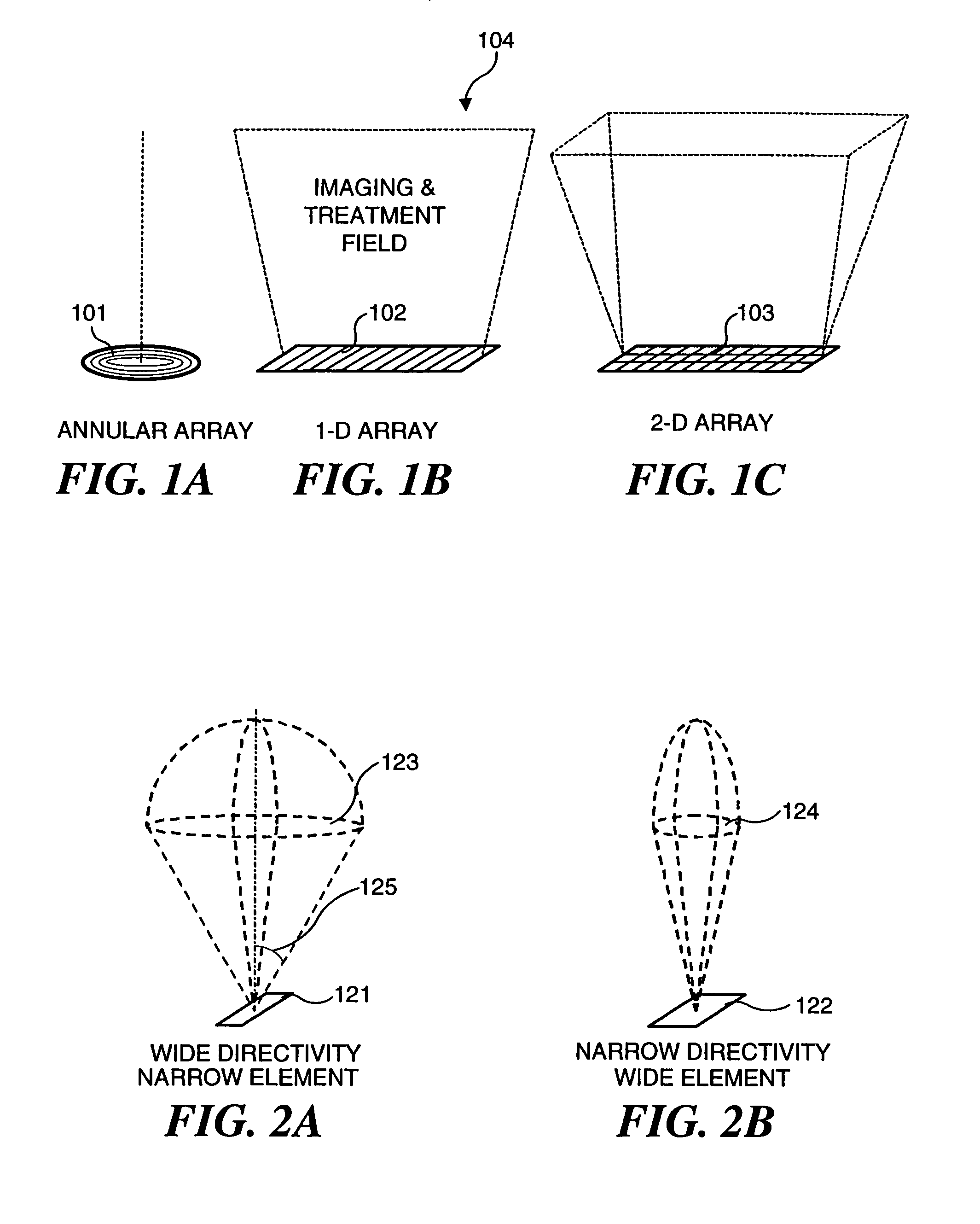
[0046]An ultrasound array includes many small transducer elements on its aperture surface, and these transducer elements can be distributed in several different geometric arrangements, as shown in FIGS. 1A–1C. Each transducer element is independently driven by its own electronic circuitry. An annular array (FIG. 1A) includes many coaxial ring elements 101. A one-dimensional (1-D) array (FIG. 1B) includes many elongate row elements 102 arranged side-by-side and extending transversely across the longitudinal axis of the array. A 1½-D or two-dimensional (2-D) array (FIG. 1C) includes a matrix of elements 103 distributed over two dimensions. The 1-D array has the advantage of simplicity and is therefore a preferred configuration for use in the present invention. The same advantages of the invention described herein can also be achieved using 1½-D and 2-D arrays. The 1-D array has a 2-D imaging and treatment field 104, or plane that extends along the longitudinal axis of the array.

[0047]...


PUM


Abstract

Ultrasound applicators able to both image a treatment site and administer ultrasound therapy include an array of transducer elements that can be focused. In several embodiments, an electronically phased array is used for controlling the focal point of an ultrasound beam. The ultrasound beam produced thereby can also be electronically steered. To reduce the quality factor or Q of the array when the array is used for imaging, an electronic switch is selectively closed, placing a resistance in parallel with each of the array elements. A flexible array is employed in several embodiments and is selectively bent or flexed to vary its radius of curvature and thus control the focal point and / or a direction of focus of the array. In another embodiment, each of the transducer elements comprising the array are individually mechanically pivotable to steer the ultrasonic beam produced by the transducer elements.

Description

RELATED APPLICATIONS[0001]This application is a divisional of U.S. application Ser. No. 09 / 747,310, filed Dec. 22, 2000, now U.S. Pat. No. 6,719,694, which claimed priority to U.S. provisional patent application, Ser. No. 60 / 171,703, filed Dec. 23, 1999, the benefit of the filing date of which is hereby claimed under 35 U.S.C. § 119(e).FIELD OF THE INVENTION[0002]The present invention generally relates to use of ultrasound for imaging and therapeutic purposes, and more specifically, to simplified ultrasound transducers that are both highly efficient for administering therapy and produce a wide bandwidth ultrasound signal for diagnostic imaging.BACKGROUND OF THE INVENTION[0003]Ultrasound is a term that refers to acoustic waves having a frequency above the upper limit of the human audible range (i.e., above 20 kHz). Because of their relatively short wavelength, ultrasound waves are able to penetrate into the human body. Based on this property, ultrasound in the frequency range of 2–20...

Claims


Application Information

Patent Timeline
Patent Type & Authority Patents(United States)
IPC IPC(8): A61B8/00A61B8/12A61B19/00A61B17/00A61B17/22A61B17/225A61B18/00A61H23/02A61N7/02G10K11/32G10K11/34H04R17/00
CPCA61B17/0057A61B8/445A61H23/0245A61N7/02G10K11/32G10K11/346A61B8/12A61B8/4461A61B2017/00907A61B2019/462A61B2019/5276A61B2019/5404A61B2019/5437A61B2562/164A61N2007/0052A61N2007/0065A61N2007/0078A61B2017/00504A61B2090/3904A61B2090/062A61B2090/378A61B2090/3937
Inventor WENG, LEEPEROZEK, DAVID M.ZHANG, JIMIN
Owner OTSUKA MEDICAL DEVICES
Why Eureka
Try Eureka