Imaging probe with combined ultrasounds and optical means of imaging

a combined ultrasound and imaging probe technology, applied in the field of imaging mammalian tissues and structures, can solve the problems of limited sensor use in the dewhurst device, poor signal penetration, and small field of view, and achieve the effect of accurately co-registering images and facilitating simultaneous imaging

Active Publication Date: 2008-07-24
SUNNYBROOK HEALTH SCI CENT
View PDF62 Cites 291 Cited by
  • Summary
  • Abstract
  • Description
  • Claims
  • Application Information

AI Technical Summary

Benefits of technology

[0042]It would be very advantageous to also provide high resolution imaging probes that combine acoustic and optical imaging onto “forward-looking” probes rather than “side-viewing” probes. It would also be helpful to provide similar probes that can look backwards, or from multiple angles in a generally side-viewing configuration.
[0043]It would also be advantageous to provide high-resolution imaging probes that combine ultrasound imaging with one or more optical imaging means.
[0044]It would also be advantageous to provide minimally invasive imaging probes that can be used for photoacoustic imaging or sonoluminescent imaging.
[0045]It would also be advantageous to provide minimally invasi

Problems solved by technology

Higher frequencies provide higher resolution but result in worse signal penetration and thus a smaller field of view.
The ultrasound sensor used in the Dewhurst device is limited to thin film polymeric piezoelectrics, such as thin film PVDF, and is used only to receive ultrasound energy, not to convert electrical energy to ultrasound.
Fiber bundles are bulky and reduce the flexibility of the shaft among other disadvantages.
However, in order to execute their study, they had to use separate catheters for each of IVUS, OCT and angioscopy imaging modalities as no catheters that combine these functions have been commercialized to date.
The OCT probes in this latter study were not suitable for in vivo use.
However, optical coherence tomography is limited by its small penetration depth (on the order of 500 to 3000 microns) in most biologic media.
Most such media are not optically transparent.
If the transducer is too small, the beam is poorly focused and has poor signal properties.
In Maschke the IVUS and OCT i

Method used


Image

  • Imaging probe with combined ultrasounds and optical means of imaging
  • Imaging probe with combined ultrasounds and optical means of imaging
  • Imaging probe with combined ultrasounds and optical means of imaging

Examples


Embodiment Construction

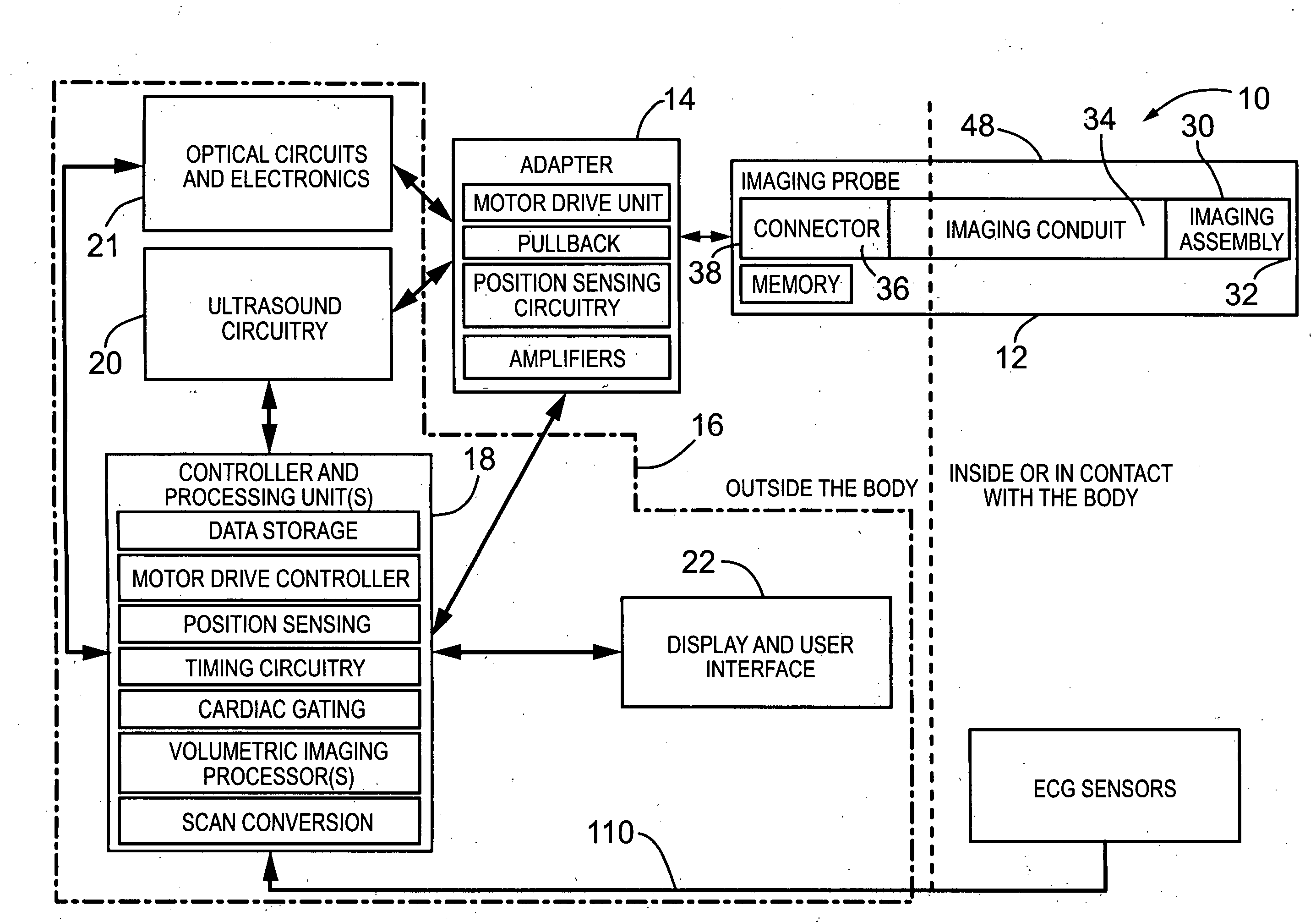
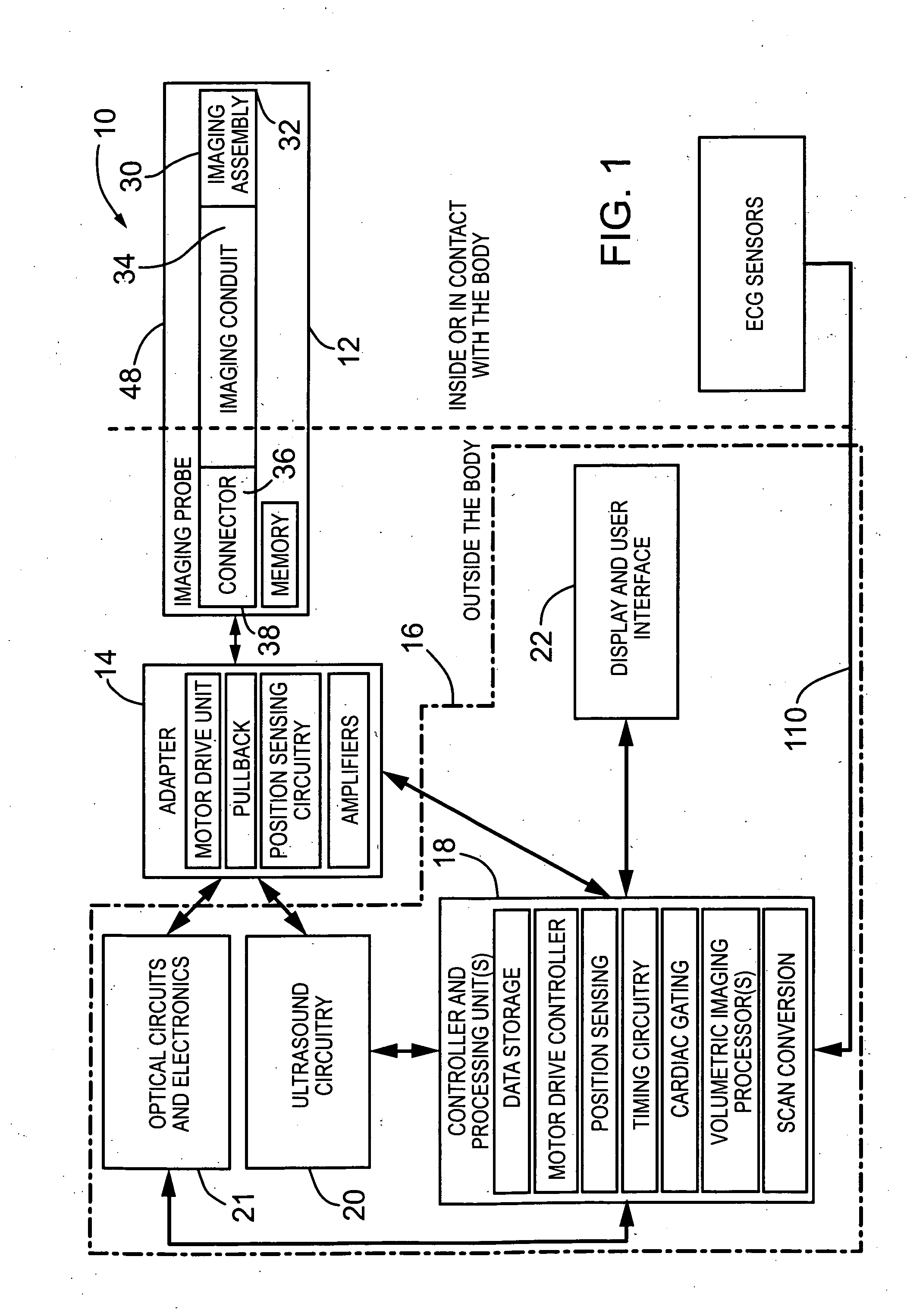
[0105]Without limitation, the majority of the systems described herein are directed to an imaging probe that enables imaging by both optical and acoustic means. As required, embodiments of the present invention are disclosed herein. However, the disclosed embodiments are merely exemplary, and it should be understood that the invention may be embodied in many various and alternative forms.

[0106]The Figures are not to scale and some features may be exaggerated or minimized to show details of particular elements while related elements may have been eliminated to prevent obscuring novel aspects. Therefore, specific structural and functional details disclosed herein are not to be interpreted as limiting but merely as a basis for the claims and as a representative basis for teaching one skilled in the art to variously employ the present invention. For purposes of teaching and not limitation, the illustrated embodiments are directed to an imaging probe that enables imaging by both optical ...


PUM


Abstract

The present invention provides an imaging probe for imaging mammalian tissues and structures using high resolution imaging, including high frequency ultrasound and optical coherence tomography. The imaging probes structures using high resolution imaging use combined high frequency ultrasound (IVUS) and optical imaging methods such as optical coherence tomography (OCT) and to accurate co-registering of images obtained from ultrasound image signals and optical image, signals during scanning a region of interest.

Description

CROSS REFERENCE TO RELATED U.S. APPLICATIONS[0001]This patent application relates to, and claims the priority benefit from, U.S. Provisional Patent Application Ser. No. 60 / 881,169 filed on Jan. 19, 2007, in English, entitled IMAGING PROBE, which is incorporated herein by reference in its entirety.FIELD OF THE INVENTION[0002]The present invention relates generally to the field of imaging mammalian tissues and structures using high resolution imaging using combined high frequency ultrasound (IVUS) and optical imaging methods such as optical coherence tomography (OCT) and to accurate co-registering of images obtained from ultrasound image signals and optical image signals during scanning a region of interest.BACKGROUND OF THE INVENTION[0003]High resolution imaging of the interior of the body (or for dermatologic or ophthalmology applications not restricted to the interior) serves multiple purposes, including any of i) assessing tissue structures, anatomy and composition; ii) planning a...

Claims


Application Information

Patent Timeline
IPC IPC(8): A61B8/12
CPCA61B5/0062A61B5/742A61B5/0095A61B5/6852A61B8/12A61B8/4281A61B8/4461A61B8/5238A61B8/543A61B1/00172A61B1/00183A61B8/483A61B8/445A61B5/0035A61B8/5292A61B5/0084A61B5/7207A61B5/0066G10K11/002A61B2562/0233A61B1/00112G02B6/3604G02B23/2423A61B1/05A61B1/04
Inventor COURTNEY, BRIANMUNCE, NIGEL ROBERTTHIND, AMANDEEP SINGHYANG, VICTOR XIAO DONGFOSTER, FRANCIS STUART
Owner SUNNYBROOK HEALTH SCI CENT
Why Eureka
Try Eureka