Method and system for providing a magnetic recording transducer having a planarized near-field transducer and a sloped pole

a near-field transducer and magnetic recording technology, applied in the field of method and system for providing magnetic recording transducers, can solve the problems of a conventional eamr transducer b>10/b> that takes these factors into consideration and may be problemati

Active Publication Date: 2013-02-26
WESTERN DIGITAL TECH INC
View PDF13 Cites 174 Cited by
  • Summary
  • Abstract
  • Description
  • Claims
  • Application Information

AI Technical Summary

Benefits of technology

[0006]FIG. 1 is depicts a conventional EAMR transducer.

Problems solved by technology

Fabrication of a conventional EAMR transducer 10 that takes these factors into consideration may be problematic.

Method used


Image

  • Method and system for providing a magnetic recording transducer having a planarized near-field transducer and a sloped pole
  • Method and system for providing a magnetic recording transducer having a planarized near-field transducer and a sloped pole
  • Method and system for providing a magnetic recording transducer having a planarized near-field transducer and a sloped pole

Examples


Embodiment Construction

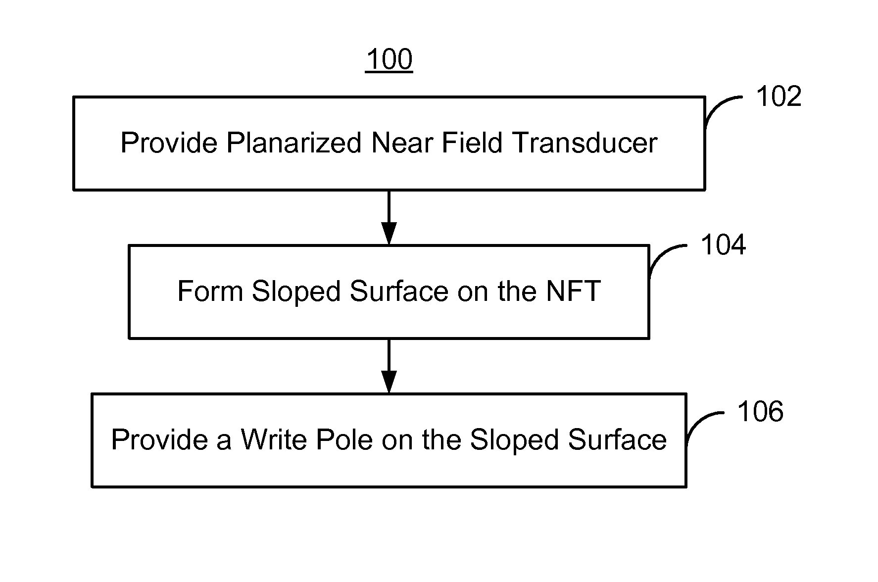
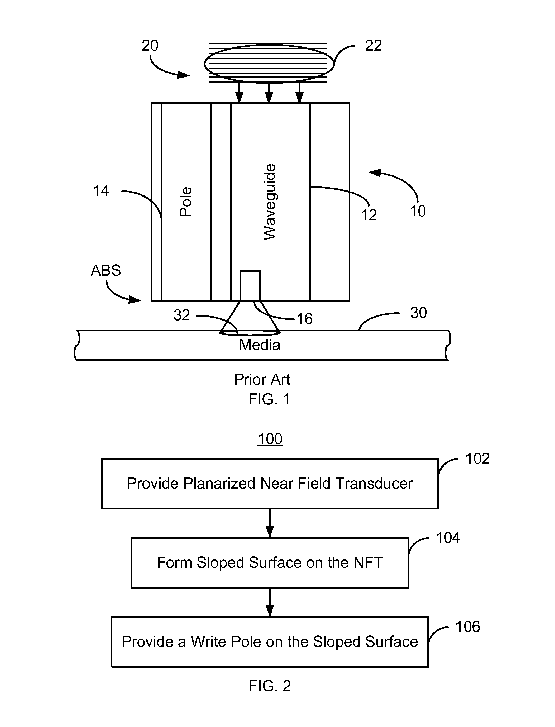
[0011]FIG. 2 is an exemplary embodiment of a method 100 for providing an EAMR transducer. For simplicity, some steps may be omitted. The method 100 is also described in the context of providing a single EAMR transducer. However, the method 100 may be used to fabricate multiple transducers at substantially the same time. The method 100 is also described in the context of particular structures. A structure or layer may include multiple materials and / or multiple sub-layers and may be formed using multiple sub-steps. The method 100 also may start after formation of other portions of the EAMR transducer. For example, the method 100 may commence after formation of a read transducer. In addition, the method may start after formation of portions of the EAMR transducer. For example, a return pole and at least a portion of the waveguide may have been formed.

[0012]A planarized NFT for the waveguide is provided, via step 102. A planarized NFT is an NFT having its top surface substantially copla...


PUM

PropertyMeasurementUnit
angleaaaaaaaaaa
angleaaaaaaaaaa
angleaaaaaaaaaa

Abstract

A method and system for fabricating an energy assisted magnetic recording (EAMR) transducer is described. The EAMR transducer has an air-bearing surface (ABS) and a waveguide. The method includes providing a planarized near field transducer (NFT) for the waveguide and forming a sloped surface on the planarized NFT. The sloped surface has a front edge separated from the ABS by a distance. The method and system also include providing a write pole on the sloped surface.

Description

BACKGROUND[0001]FIG. 1 depicts a portion of a conventional energy assisted magnetic recording (EAMR) transducer 10. The conventional EAMR transducer 10 is used in writing to recording media 30. To do so, the conventional EAMR transducer 10 receives light, or energy, from a conventional laser (not shown in FIG. 1). Also shown is grating 20. The conventional EAMR transducer 10 includes a conventional waveguide 12, conventional pole 14, and a conventional near-field transducer (NFT) 16. Also shown is a laser spot 22 on the gratings 20. Other components that may be part of the conventional EAMR transducer 10 are not shown.[0002]In operation, the light from the spot 22 on the grating 20 is coupled to the conventional waveguide 12. The conventional waveguide 12 guides the light to the conventional NFT 16 near the air-bearing surface (ABS). The conventional NFT 16 focuses the energy from the waveguide 12 to an optical spot 32 on the media 30. A small region of the conventional media 30 is ...

Claims


Application Information

Patent Timeline
Patent Type & Authority Patents(United States)
IPC IPC(8): G11B11/00
CPCG11B5/3163G11B5/6088G11B2005/0021
Inventor HU, YUFENGTRAN, UT
Owner WESTERN DIGITAL TECH INC
Why Eureka
Try Eureka