
Ski-chair-lift display apparatus and method

a technology of display apparatus and ski chair, which is applied in the field of ski chairlifts, can solve the problems of considerable time spent idle, considerable time spent in waiting in line at some resorts, and virtually stationary position of the chair, and achieves the effects of reducing thickness, convenient removal, and convenient removal

Active Publication Date: 2013-03-05
AHRENS CHRISTIAN R
View PDF4 Cites 3 Cited by
  • Summary
  • Abstract
  • Description
  • Claims
  • Application Information

AI Technical Summary

Benefits of technology

The patent describes a display system that can be easily attached to a chair lift system and removed when the season ends. The system includes brackets that can be stacked together to save space during storage. The system can be reassembled and re-attached to the chairs in a simple and efficient way. The technical effects of this system are that it allows for easy removal and storage of the display panels, while minimizing damage and wear. Additionally, the system makes efficient use of space by allowing the panels to be stacked and stored with minimal space.

Problems solved by technology

However, considerable time is spent in a virtually stationary position in the chair.
Moreover, considerable time is spent waiting in line at some resorts.
Thus, considerable time is spent idle.
Typically, users may have only limited time to review area maps posted on signs about a ski resort.
Folded maps are necessarily problematic.
Removing bulky gloves to unfold a map and fold it up again is not highly effective, and can be very uncomfortable.
Thus, riders are exposed to wind and cold.
Removing gloves and mittens while riding a chair life is hardly recommended due to the cold weather.
Riding a lift a user or rider is provided only limited opportunity for movement and thus is exposed to full force of the prevailing climate, which is typically cold to support the necessary environment for a ski resort.
Meanwhile, riders have a limited time upon completing a run to review a larger area map posted on signage at the resort.

Method used


Image

  • Ski-chair-lift display apparatus and method
  • Ski-chair-lift display apparatus and method
  • Ski-chair-lift display apparatus and method

Examples


Embodiment Construction

[0033]It will be readily understood that the components of the present invention, as generally described and illustrated in the drawings herein, could be arranged and designed in a wide variety of different configurations. Thus, the following more detailed description of the embodiments of the system and method of the present invention, as represented in the drawings, is not intended to limit the scope of the invention, as claimed, but is merely representative of various embodiments of the invention. The illustrated embodiments of the invention will be best understood by reference to the drawings, wherein like parts are designated by like numerals throughout.

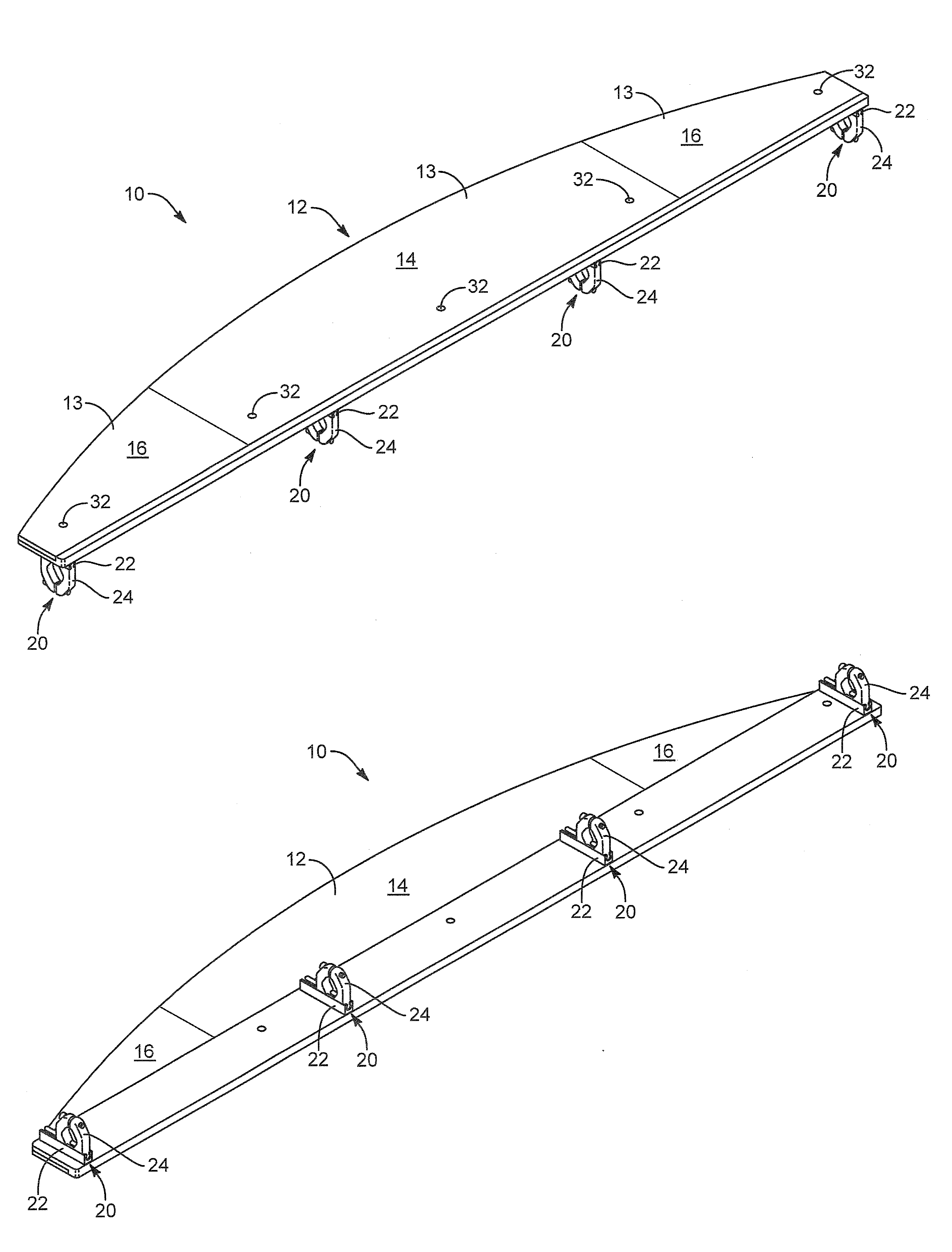
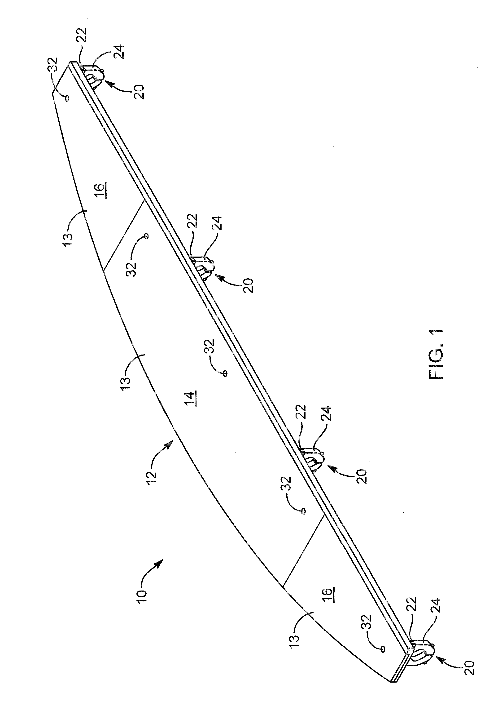
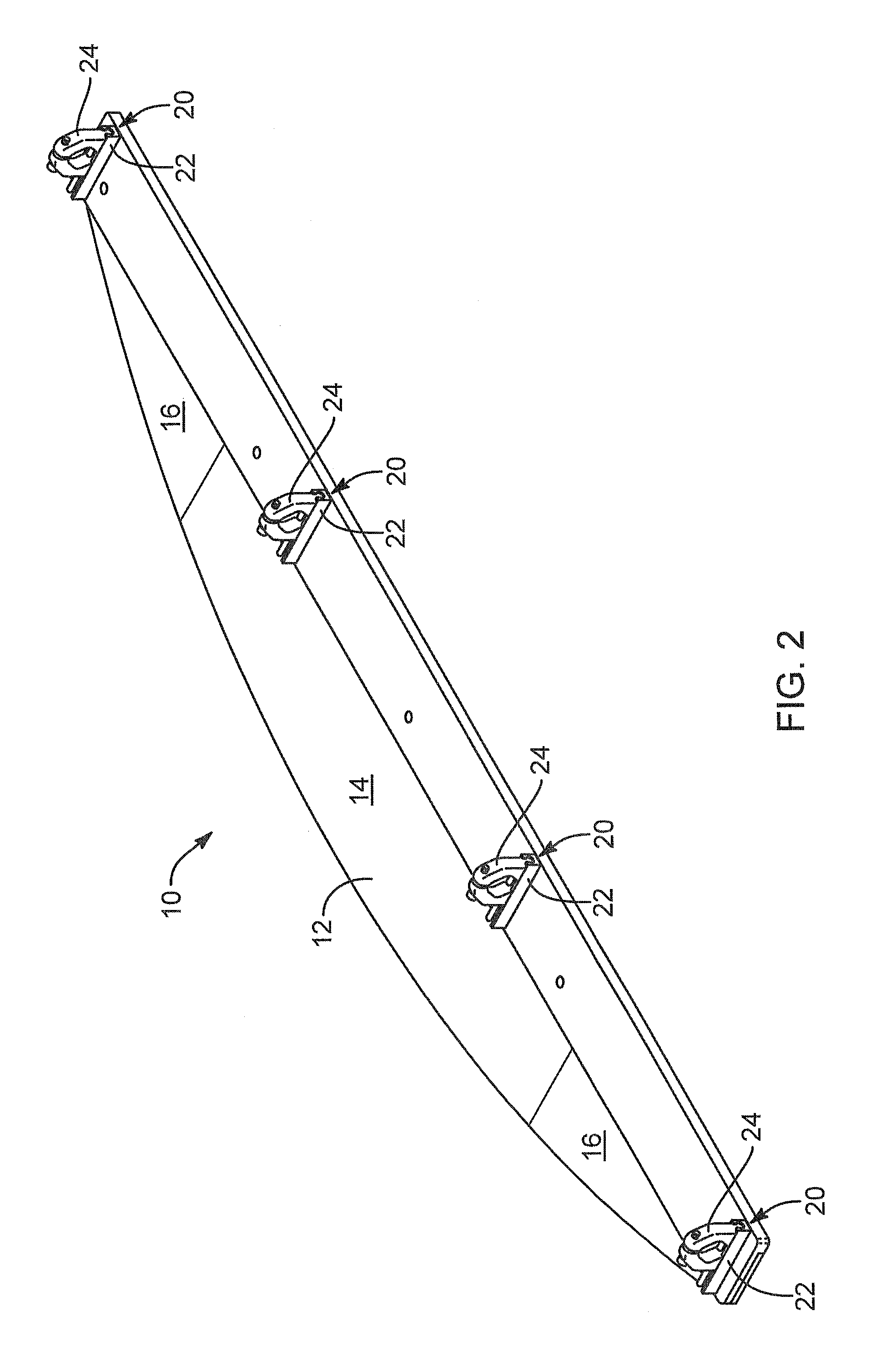
[0034]Referring to FIGS. 1-10, an apparatus 10 or system 10 in accordance with the invention may include a display 12 or a panel 12. The display 12 may be divided into regions 13 generally, including information regions 14 and advertising regions 16. Each information region 14 may be designated for display of particular informat...


PUM

PropertyMeasurementUnit
total thicknessaaaaaaaaaa
diametersaaaaaaaaaa
diametersaaaaaaaaaa

Abstract

A display system is easily attached to the safety bar of a chair on a chair lift system at the beginning of a season. The display system includes brackets formed of rails holding clamp portions that may be fastened together to clamp the display system to a chair, such as to the safety bar across the lap of a rider. At the end of a season, the display system may be removed from each chair, the clamp portions removed, and the display systems stacked. In one simplified system, adjacent displays may be stacked back to back, and such adjacent pairs may be stacked with the displays in adjacent pairs positioned face-to-face. Thus, metal brackets on the backs need not scratch up the reading faces or surfaces. Meanwhile, the displays may be stored in minimal space, with great stability, while minimizing wear and damage.

Description

BACKGROUND[0001]1. The Field of the Invention[0002]This invention relates to ski lifts and in particular to informational displays available and presented to riders on a chair lift system.[0003]2. The Background Art[0004]Riders of ski chair lifts may spend considerable time riding a lift up a mountain side to the beginning of a particular run or series of runs, before skiing down one or more of those runs to the bottom to repeat the exercise. While skiing, a skier does exercise and may maintain body warmth by virtue of that exercise. However, considerable time is spent in a virtually stationary position in the chair. Moreover, considerable time is spent waiting in line at some resorts. Thus, considerable time is spent idle.[0005]Typically, users may have only limited time to review area maps posted on signs about a ski resort. Instead, a user or rider of a ski lift may typically have a folded map in a pocket. Folded maps are necessarily problematic. Removing bulky gloves to unfold a...

Claims


Application Information

Patent Timeline
Patent Type & Authority Patents(United States)
IPC IPC(8): B61B3/00G09F7/00
CPCB61B12/002G09F23/02B23P19/00B61B7/00G09F3/16G09F2007/1856Y10T29/49815G09F2023/005
Inventor AHRENS, CHRISTIAN R
Owner AHRENS CHRISTIAN R
Learn More