Screen device and fastening means for screen plates

a screen plate and fastening technology, applied in the direction of screening, screening, grading, etc., can solve the problems of only achieving the parallelism of the bearing surface of the screwed surface, affecting the quality of the screen plate, so as to achieve easy and fast replacement, less susceptible to vibration, and reliable

Active Publication Date: 2013-03-05
LINDNER MANUEL
View PDF6 Cites 0 Cited by
  • Summary
  • Abstract
  • Description
  • Claims
  • Application Information

AI Technical Summary

Benefits of technology

[0012]The screen plate is thus fastened to the screen carrier without screws by the forces applied by the first and the second tensioning element. As at least one of the tensioning elements exerts an elastic restoring force (that means that it reacts to an applied force by exerting a reaction force), the claimed fastening means are advantageous in that the fastening of the screen plate (screen) is less susceptible to vibrations than in prior art, i.e. the fastening is more reliable.
[0013]Moreover, a screen plate fastened with the claimed fastening means can be easily and quite quickly replaced by a new one after it has worn down in the course of the operation of the comminuting device. Furthermore, the provision of an elastic tensioning element which exerts the elastic force (for example a spring restoring force) permits greater work tolerances of the individual components of the screen device, as variances in the manufacture can be compensated by correspondingly adjusting the elastic tensioning element (the elastic restoring force).
[0015]The elastic tensioning element can be in particular a spring element or at least comprise one. The spring element can be a pressure spring, a leaf spring, a flat spiral spring or else a rubber element which are well-known in prior art. The use of such a spring element for applying the elastic restoring force for fastening the screen plate by tensioning is inexpensive, practicable and permits a reliable fastening of the screen plate to the screen carrier.

Problems solved by technology

While the comminutor is operated, the screwed joints are subjected to high stresses, and thus, the bearing surfaces of the screwed surfaces must be as parallel as possible with respect to each other to prevent, if possible, the screwed joints from getting released or being broken, resulting in severe damages of the complete comminuting device in operation.
The parallelism of the bearing surfaces of the screwed surfaces can only be achieved if the screen cassette and the screen plates are manufactured with very small tolerances.
Thereby, the manufacture of these components is very expensive.
A further disadvantage of the screwed fastening of the screen plates in prior art is that the screwed joints are sometimes very difficult to access.
As the screen plates are subject to wear and thus must be maintained regularly, the possibly hardly accessible screwed joints must be released and replaced by a serviceman at regular intervals, which is very time-consuming.

Method used


Image

  • Screen device and fastening means for screen plates
  • Screen device and fastening means for screen plates

Examples


Embodiment Construction

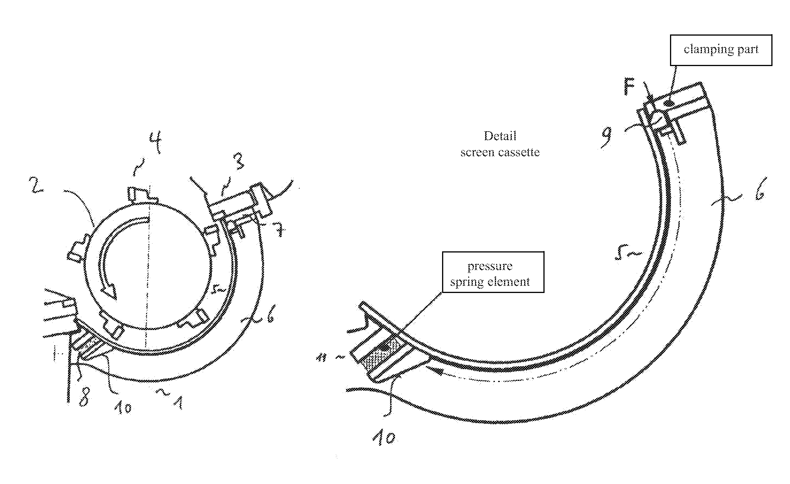
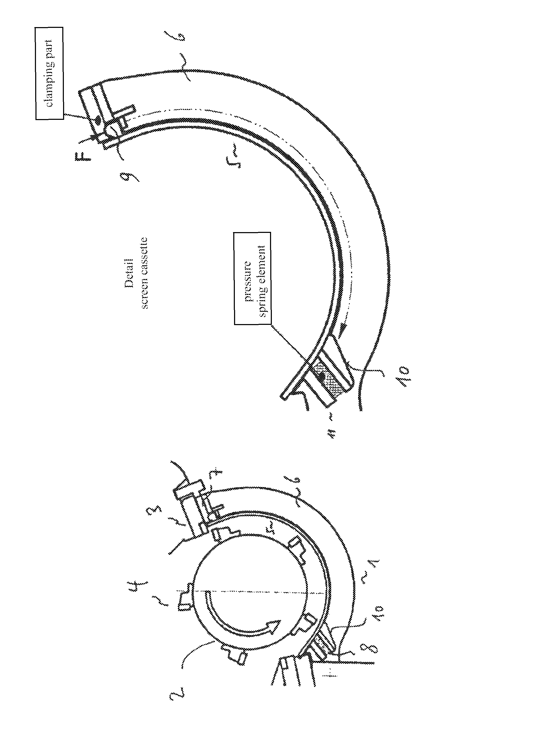
[0033]It should be mentioned first that the terms “screen plate” and “screen” are employed in this application as synonyms, and the term “screen plate” shall in particular not express any restriction of the material of the screen. Equally, the terms “screen cassette” and “screen carrier” are employed as synonyms, and the term “screen cassette” shall not express any geometric or other restriction with respect to the neutral term of the carrier.

[0034]As is shown in FIG. 1, a comminuting device shown in a section comprises a screen device 1 which partially surrounds a rotor 2 (rotating counterclockwise in the shown example). At the upper right end of the screen device 1, there is a stator knife 3 which comminutes loaded material in cooperation with the rotating knives 4 attached to the rotor 2. A screen plate 5 having a predetermined perforation (here, various shapes, such as a honeycomb shape, are possible) is fastened to a screen carrier 6 by means of a clamping part 7 and a pressure...


PUM

PropertyMeasurementUnit
sizeaaaaaaaaaa
forceaaaaaaaaaa
elastic restoring forceaaaaaaaaaa

Abstract

The present invention relates to fastening means for fastening a screen plate onto a screen carrier of a screen device for a comminuting device, comprising a first tensioning element, which is connected to the screen device, particularly to the screen carrier, and which is designed to exert a force on the screen plate; a second tensioning element, which is connected to the screen device, particularly the screen carrier, and which is designed to exert a force on the screen plate, wherein at least one of the tensioning elements is an elastic element, which is designed to exert an elastic restoring force on the screen plate such that the screen plate is tensioned between the first and the second tensioning elements. The invention further relates to a method for fastening a screen plate onto a screen carrier of a screen device for a comminuting device.

Description

FIELD OF THE INVENTION[0001]The present invention relates to a screen device for a comminuting device by means of which comminuted components are discharged, and in particular fastening means for fastening screen plates to screen cassettes.BACKGROUND OF THE INVENTION[0002]Commercial waste, industrial waste, domestic waste, etc., e.g. (hard) plastics, textiles, composites, wheels, rubber or scrap wood (such as pallets and particle boards) must be comminuted in corresponding comminuting devices before they are definitively disposed of or in particular before they are returned to the cycle of valuable substances.[0003]A central element of a conventional comminutor is a rotor unit which comprises a rotor equipped with knives which can be provided e.g. with concavely ground circular cutting crowns. The knives are fastened to knife holders, for example by screwing, which are welded into knife recesses or can be screwed, for example, the recesses being milled into the rotor. The comminutio...

Claims


Application Information

Patent Timeline
Patent Type & Authority Patents(United States)
IPC IPC(8): B02C18/22
CPCB02C18/145B02C23/08B07B1/20B07B1/48Y10T29/49826B07B2201/02B02C2023/165
Inventor SCHIFFER, PETERFRITZ, MARIOTIEFNIG, EGON
Owner LINDNER MANUEL
Why Eureka
Try Eureka