Turning sheet moving machine for transformer cooling fin production line
A technology for heat sinks and production lines, which is applied to the field of turning sheet shifting machines for transformer heat sink production lines, can solve the problems of easy falling of transformer heat sinks, reduced performance, deformation of heat sinks, etc., so as to improve work efficiency and performance, and is not easy to fall off. The effect of falling and clamping stability
- Summary
- Abstract
- Description
- Claims
- Application Information
AI Technical Summary
Problems solved by technology
Method used
Image
Examples
Embodiment 1
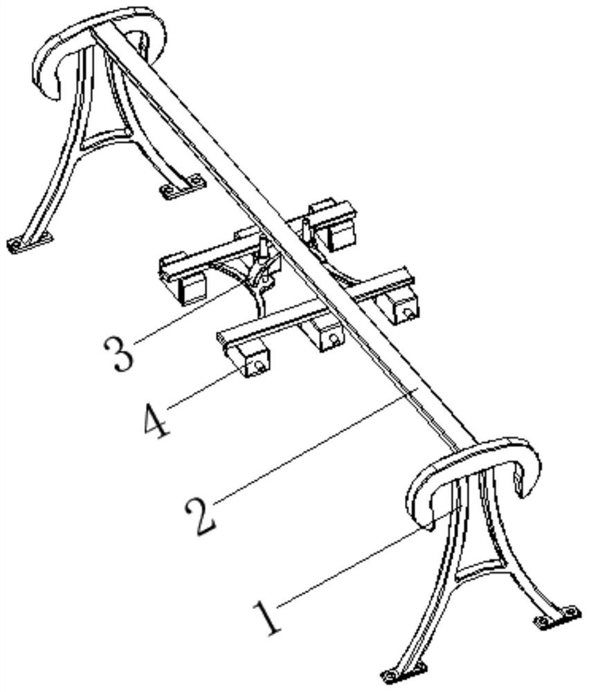
[0029] see Figure 1-Figure 6 , the present invention provides a technical solution: a turning sheet shifting machine for a transformer heat sink production line, comprising a frame 1, a linear drive mechanism 2, a support device 3, and a clamping device 4, and the linear drive mechanism 2 is arranged on the surface of the frame 1. On the top, the support device 3 is arranged at the bottom output end of the linear drive mechanism 2, and the clamping device 4 is arranged at the bottom of the support device 3;
[0030] The support device 3 is provided with an arc-shaped connecting frame 31, an electric telescopic rod 32, a connecting reinforcing rib 33, and a cross beam 34. The top of the arc-shaped connecting frame 31 is arranged at the bottom output end of the linear drive mechanism 2, and the surface of the electric telescopic rod 32 is fixed on the On the surface of the arc-shaped connecting frame 31, the top of the connecting reinforcing rib 33 is fixedly connected with the...
Embodiment 2
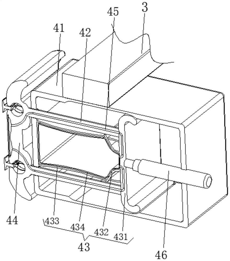
[0032] The clamping device 4 is provided with a casing 41 , a connecting sliding rod 42 , a pressure receiving device 43 , a clamping device 44 , an air passage 45 , and a cylinder 46 . The top of the casing 41 is fixedly connected with the bottom of the supporting device 3 , and the connecting sliding rod 42 The sliding connection is on the surface side of the housing 41 , the pressure receiving device 43 is arranged inside the housing 41 and close to the position of the connecting slide bar 42 , the clamping device 44 is arranged at the end of the connecting slide bar 42 , and the air passage 45 is opened at the Connecting the inner central position of the sliding rod 42, the cylinder 46 is arranged inside the casing 41 and close to the position of the pressure-receiving device 43;
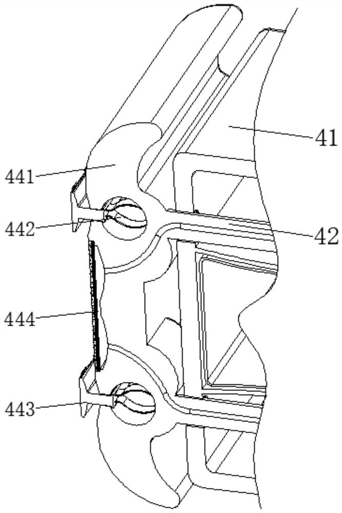
[0033] The clamping device 44 is provided with a clamping base plate 441, a curved elastic member 442, a chuck device 443, and an expansion device 444. The surface side of the clamping base plate...
Embodiment 3
[0036] The pressure receiving device 43 is provided with a sliding plate 431 , a top pressing piece 432 , an arc-shaped elastic piece 433 , and an elastic bladder 434 . Fixed connection, one end of the top pressure piece 432 is fixedly connected to the surface of the sliding plate 431 and away from the cylinder 46 side, the arc-shaped elastic piece 433 is arranged between the inner wall of the housing 41 and the two sides corresponding to the end of the top pressure piece 432, elastic The bladder 434 is disposed between the inner wall of the casing 41 and the two sides corresponding to the surface of the top pressing member 432 and is close to the arc-shaped elastic piece 433 .
[0037] The expansion device 444 is provided with an air cavity 4441, an elastic film 4442, and an anti-skid layer 4443. The air cavity 4441 is opened at the center of the surface of the clamping substrate 441. The air port of the air cavity 4441 is communicated with one end of the air passage 45. Tigh...
PUM
 Abstract
Description
Claims
Application Information
 - R&D
- Intellectual Property
- Life Sciences
- Materials
- Tech Scout
- Unparalleled Data Quality
- Higher Quality Content
- 60% Fewer Hallucinations
Browse by: Latest US Patents, China's latest patents, Technical Efficacy Thesaurus, Application Domain, Technology Topic, Popular Technical Reports.
© 2025 PatSnap. All rights reserved.Legal|Privacy policy|Modern Slavery Act Transparency Statement|Sitemap|About US| Contact US: help@patsnap.com


