Laser focusing adjustment system for realizing interaction with 360-degree configuration of directional beam line

A focus adjustment and beam line technology, applied in laser welding equipment, metal processing equipment, welding equipment, etc., to achieve the effect of reducing cost, low vibration and flexible operation

Active Publication Date: 2021-01-12
SHANGHAI INST OF OPTICS & FINE MECHANICS CHINESE ACAD OF SCI
View PDF9 Cites 0 Cited by
  • Summary
  • Abstract
  • Description
  • Claims
  • Application Information

AI Technical Summary

Problems solved by technology

If the focus adjustment optical path of the laser is built based on the general method, not only need to face the cost problem caused by processing a large number of ultra-large optical lenses and ultra-large vacuum cavity, but also face the difficulty of flexibly adjusting the optical path to realize the multi-dimensional alignment with the directional beamline. The Dilemma of the Experimental Requirements of Isotype Interactions

Method used


Image

  • Laser focusing adjustment system for realizing interaction with 360-degree configuration of directional beam line
  • Laser focusing adjustment system for realizing interaction with 360-degree configuration of directional beam line
  • Laser focusing adjustment system for realizing interaction with 360-degree configuration of directional beam line

Examples


Embodiment Construction

[0024] In order to make the above-mentioned advantages of the present invention clearly understandable, the specific implementation manners of the present invention will be described in detail below in conjunction with the accompanying drawings. It should be noted that the present invention should not be limited to the following specific implementation content, and those skilled in the art should understand the present invention from the spirit embodied in the following embodiments, and each technical term can be based on the spirit of the present invention. Do the broadest understanding.

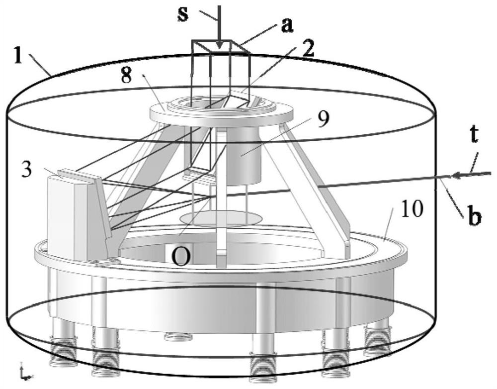
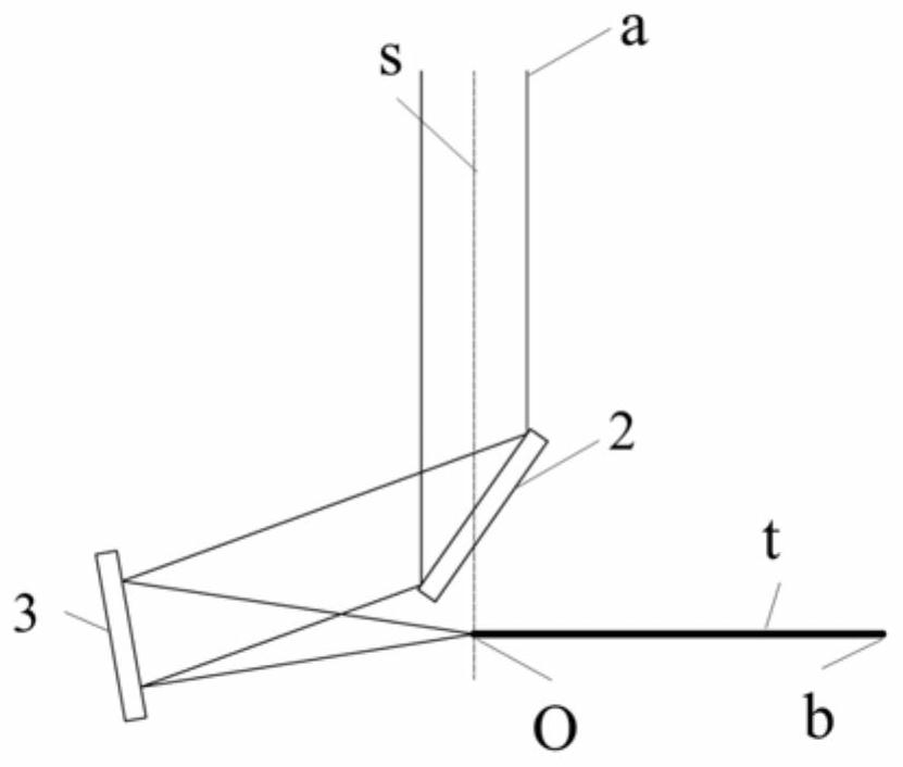
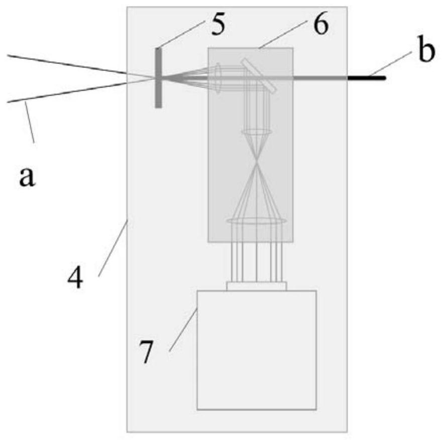
[0025] figure 1 Shown is a schematic structural diagram of a laser focus adjustment system for realizing 360° position-type interaction with a directional beamline according to the present invention. Fig. 2 shows the specific laser beam focusing optical path and laser and directional beam line alignment optical path in the present invention. As shown in the two figures, the present invent...


PUM


Abstract

The invention discloses a laser focusing adjustment system for realizing the interaction with the 360-degree configuration of a directional beam line. The laser focusing adjustment system comprises afocusing light path, a focal spot detection alignment system and a vacuum cavity. According to the laser focusing adjustment system for realizing the interaction with the 360-degree configuration of the directional beam line provided by the invention, a laser light is initially and vertically transmitted from top to bottom, an optical axis is s, the directional beam line is transmitted along the horizontal direction, a central axis is t, and the axis s and the axis t intersect at a point O (a fixed laser focal spot position). According to the laser focusing adjustment system for realizing theinteraction with the 360-degree configuration of the directional beam line provided by the invention, a planar mirror (the reflection angle is M, and the M is more than 45 degrees and less than 90 degrees) is used for deflecting the laser light to the side lower part, and then the laser light is reflected by an off-axis paraboloidal mirror (the off-axis angle is N, and the N is equal to 2M-90 degrees) along the horizontal direction and is focused at the point O under the assistance of the focal spot detection alignment system. The planar mirror and the off-axis paraboloidal mirror are stably supported on a three-dimensional pagoda platform. The planar mirror and the off-axis paraboloidal mirror synchronously rotate along the axis s, so that the interaction of the laser light and the 360-degree configuration of the directional beam line at the point O is realized. The laser focusing adjustment system for realizing the interaction with the 360-degree configuration of the directional beamline provided by the invention has the characteristics of simple optical path, low cost, flexible operation and the like.

Description

technical field [0001] The invention relates to the field of interaction between relativistic laser and plasma, specifically, it is a device for completing laser focusing and realizing 360° interaction with another directional beamline. Background technique [0002] In recent years, with the vigorous development of laser technology, especially the invention of chirped pulse amplification technology, the laboratory has been able to obtain more than 10 22 W / cm 2 , Relativistic intensity laser pulse with a single pulse width less than 10fs, such a strong laser can rapidly ionize matter to form plasma, and the interaction between laser and matter enters the field of strong relativistic nonlinear optics. Through laser plasma interaction, high-quality (high energy, high current intensity, low energy dispersion, high collimation) electron sources, ion sources and X / gamma ray sources can be obtained. Such particle sources are used in biomedicine, chemical materials, high energy phy...

Claims


Application Information

Patent Timeline
Patent Type & Authority Applications(China)
IPC IPC(8): B23K26/046B23K26/06B23K26/70
CPCB23K26/046B23K26/0643B23K26/702
Inventor 沈百飞徐同军
Owner SHANGHAI INST OF OPTICS & FINE MECHANICS CHINESE ACAD OF SCI
Why Eureka
Try Eureka