Check patentability & draft patents in minutes with Patsnap Eureka AI!

Oil mist separator

a technology of oil mist separator and separator plate, which is applied in the direction of separation process, filtration separation, auxillary pretreatment, etc., can solve the problems of corresponding backpressure increase, insufficient work of impactor separator, and insufficient work, so as to achieve long service life, high separation efficiency, and acceptable pressure loss

Inactive Publication Date: 2013-03-05
MAHLE INT GMBH
View PDF36 Cites 9 Cited by
  • Summary
  • Abstract
  • Description
  • Claims
  • Application Information

AI Technical Summary

Benefits of technology

The present invention is aimed at providing an improved oil mist separator design that is cost-effective, compact, and has a long maintenance-free service life. It offers an optimal pressure loss and high separation efficiency. The invention includes an impactor separator that works by redirecting the flow of gas using an impact wall or plate, which causes liquid particles to adhere to the impact wall and flow off. This impactor separator only comes into play when there is a high differential pressure, which prevents backpressure and allows for the separation of liquid particles from gas. In the oil mist separator, a valve body acting as a flow directing element can be used to further improve the separation efficiency. The oil mist separator also has a collection chamber for collecting the oil that flows off from the filter material, which can be conveyed out of the housing without the need for a return valve. Additionally, the invention includes a replaceable filter cartridge that can be easily installed and maintained.

Problems solved by technology

To achieve the desired high separation efficiency, however, the impactor separator needs a comparatively high flow velocity which can normally be achieved by means of a cross-section reduction, in particular by means of a nozzle formation which, however, results in a corresponding backpressure increase.
Thus, in case of low differential pressures, such an impactor separator does not work at all or only insufficiently.

Method used


Image

  • Oil mist separator
  • Oil mist separator
  • Oil mist separator

Examples


Embodiment Construction

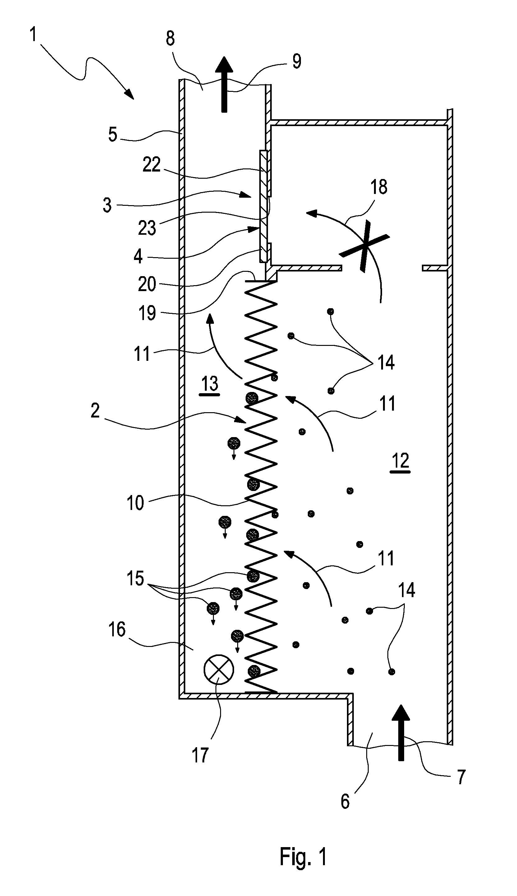
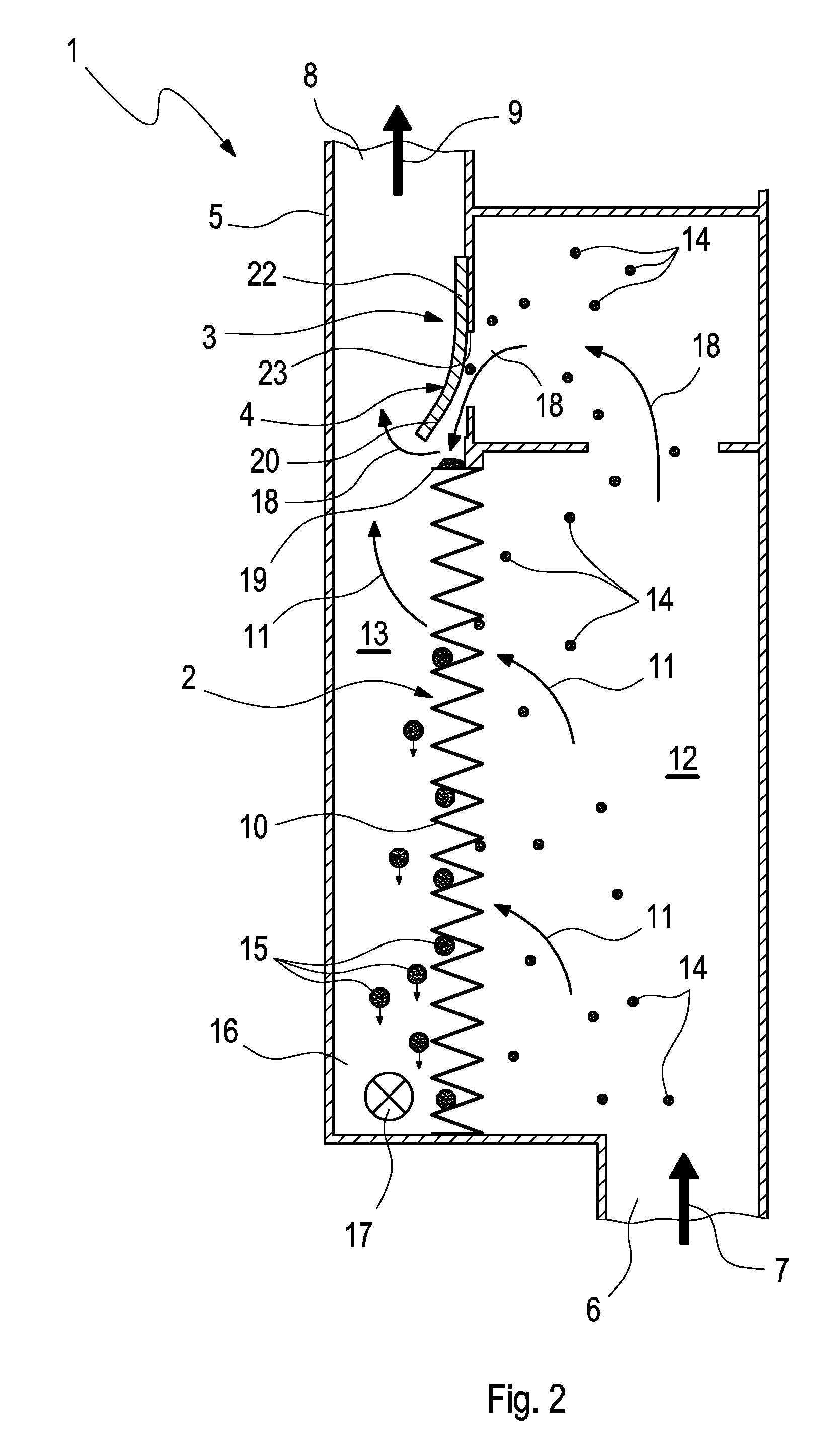
[0027]According to the FIGS. 1 to 6, an oil mist separator 1 comprises a first separator unit 2 and a second separator unit 3, and a bypass valve 4. The oil mist separator 1 is provided for a use in a positive crankcase ventilation system or forms an integral part of such a positive crankcase ventilation system. For this, the oil mist separator 1 is integrated in a vent line which connects a crankcase with a fresh gas tract of an internal combustion engine which can be arranged in particular in a motor vehicle. By means of the negative pressure prevailing within the intake tract, blow-by gas is exhausted from the crankcase. Oil mist and, if any, solid particles such as, e.g., soot carried along in the blow-by gas are separated from the blow-by gas by means of the oil mist separator 1. For this purpose, blow-by gas flows through the oil mist separator 1. A housing 5 of the oil mist separator 1 has an inlet 6 through which blow-by gas flows in according to arrow 7, and an outlet 8, th...


PUM

PropertyMeasurementUnit
differential pressureaaaaaaaaaa
pressureaaaaaaaaaa
pressure lossaaaaaaaaaa

Abstract

A positive crankcase ventilation oil mist separator system has a first separator unit, wherein the first separator unit includes at least one filter body arranged in a blow-by gas path such that blow by gas flows through the filter body; a second separator unit, wherein the second separator is an impactor separator arranged in a bypass path that bypasses the first separator unit; and a bypass valve, which opens the bypass path as soon as a differential pressure at the first separator unit exceeds a predefined value, wherein the second separator unit comprises an impact wall formed by a section of the filter body of the first separator unit, and a flow directing element which directs the blow-by gas flow against the impact wall when the blow-by gas path is open.

Description

CROSS-REFERENCES TO RELATED APPLICATIONS[0001]This application claims priority to German patent applications DE 10 2007 062 098.7 filed on Dec. 21, 2007, and PCT / EP2008 / 067081 filed on Dec. 9, 2008, both of which are hereby incorporated by reference in their entirety.TECHNICAL FIELD[0002]The present invention relates to an oil mist separator for a positive crankcase ventilation unit.BACKGROUND[0003]During the operation of internal combustion engines which, for example, can be arranged in motor vehicles, so-called blow gas gets through a leakage between pistons and cylinders into a crankcase of the respective internal combustion engine. To prevent unacceptable overpressure within the crankcase or to prevent emission of blow-by gas into the environment, positive crankcase ventilation systems are used. Usually, such a positive ventilation system connects the crankcase by means of a vent line with a fresh gas tract of an internal combustion engine. Within the fresh gas tract, in particu...

Claims


Application Information

Patent Timeline
Patent Type & Authority Patents(United States)
IPC IPC(8): B01D46/00
CPCB01D45/04B01D46/002B01D46/0021B01D46/003B01D46/0087B01D46/10B01D46/2411F01M13/04F01M2013/0044F01M2013/0055F01M2013/0066F01M2013/0433F01M2013/0438B01D46/60B01D46/58
Inventor ENDERICH, ANDREASFEIL, MICHAELFRUH, WOLFGANGHUTTER, ULRICHRUPPEL, STEFANSAUTER, HARTMUTOZKAYA, YAKUP
Owner MAHLE INT GMBH
Features
  • R&D
  • Intellectual Property
  • Life Sciences
  • Materials
  • Tech Scout
  • Unparalleled Data Quality
  • Higher Quality Content
  • 60% Fewer Hallucinations
Learn More