Battery isolator unit

a battery isolation and battery technology, applied in the direction of electric vehicles, electric devices, electrical equipment, etc., to achieve the effect of reducing the duty cycle of the control signal

Active Publication Date: 2013-03-05
REDARC TECH
View PDF27 Cites 12 Cited by
  • Summary
  • Abstract
  • Description
  • Claims
  • Application Information

AI Technical Summary

Benefits of technology

[0033]In an embodiment, if difference between the present difference value and the previous difference value does not exceed a first predetermined difference value for a continuous time period, the target duty cycle may be reduced by an adjustment value at the expiry of the time period. Hence, an embodiment of the present invention includes a counter means which is cycled on each comparison of the present difference value with the previous difference value if the difference between the present difference value and the previous difference value is less than the first predetermined difference value, and a means for reducing the duty cycle of the control signal after a predetermined number of counter cycles. The counter may include an up-counter or a down-counter.
[0044]Embodiments of the present invention may provide a battery isolator unit which requires a reduced power consumption to maintain a switch element in a closed position during normal operation by regulating the bias holding the switch element in the closed position. Furthermore, embodiments of the present invention may be able to respond to voltage disturbances across the switch element caused by vibration, movement or the like so as to increase the bias of the switch, when required, to maintain or hold the switch in the closed position.

Problems solved by technology

When the current through the coil falls below the holding current, the coil is insufficiently driven or energised to provide a minimum holding force required to bias or hold the armature in the actuated position and thus the armature returns to the non-actuated position.

Method used


Image

  • Battery isolator unit
  • Battery isolator unit
  • Battery isolator unit

Examples


Embodiment Construction

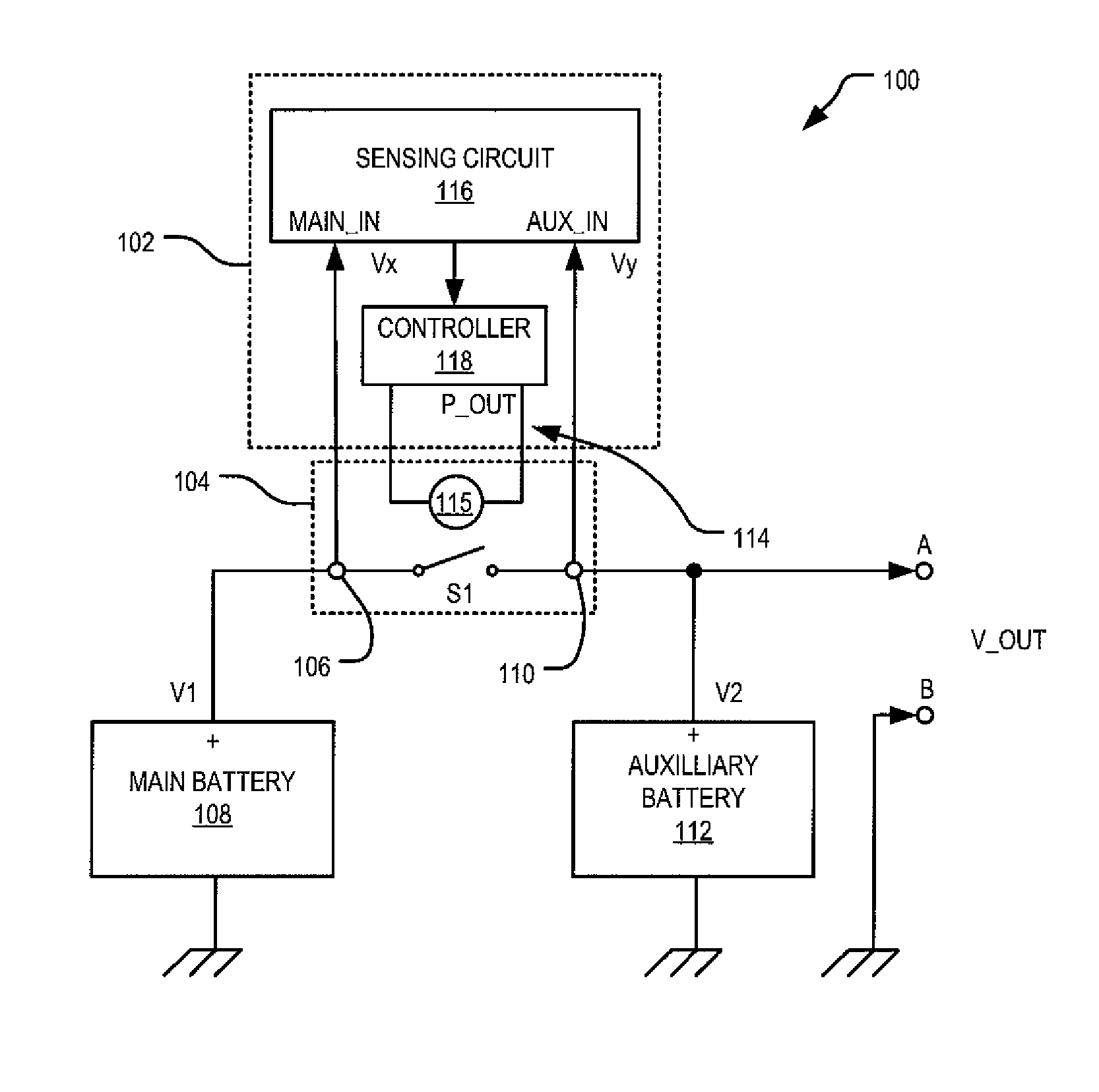
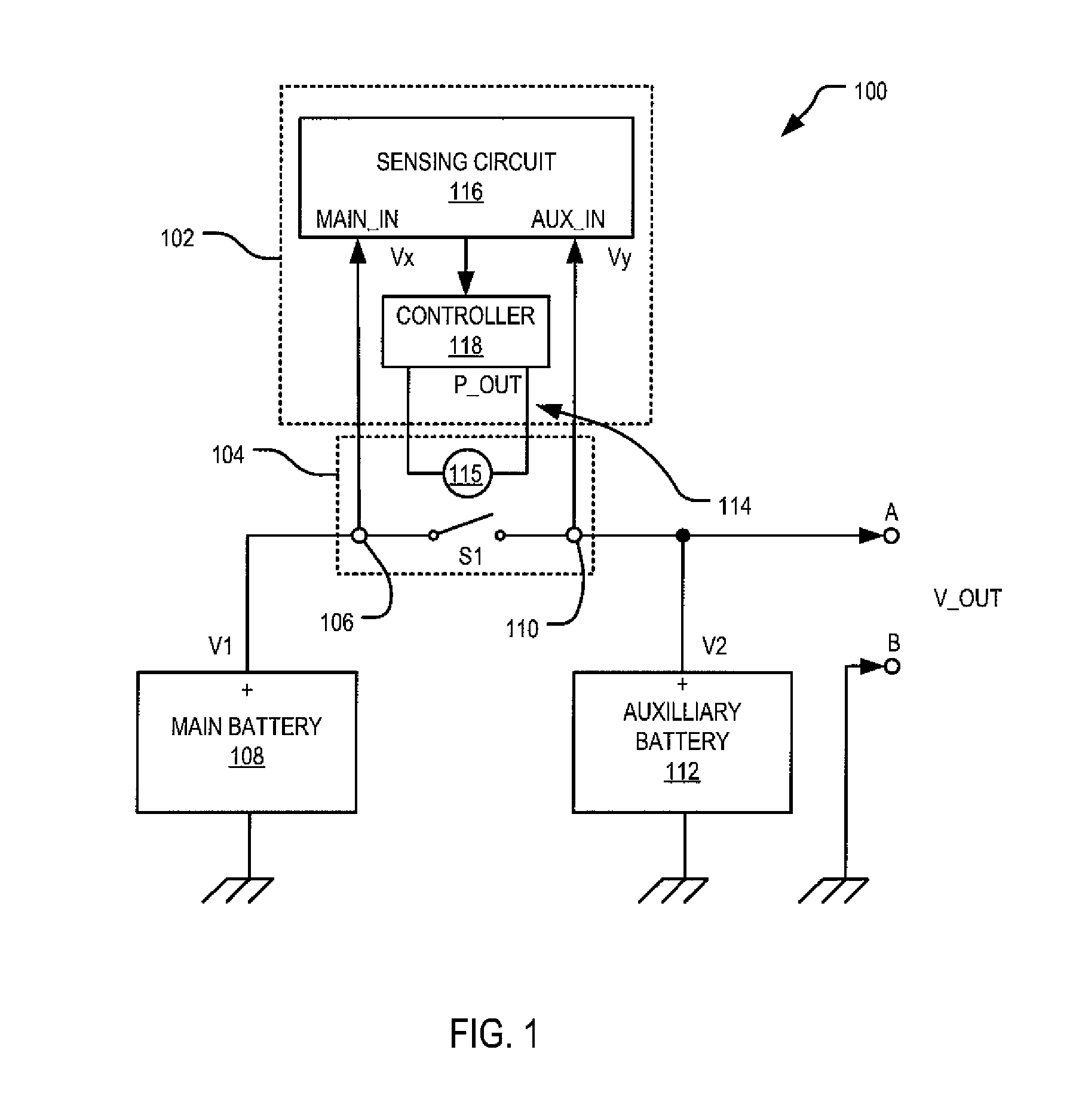
[0052]Turning initially to FIG. 1 there is shown a block diagram for an automotive electrical power supply system 100 which incorporates a battery isolator unit 102 according to an embodiment. The battery isolator unit 102 illustrated in FIG. 1 is shown as electrically connected to a switching means 104 having a first contact 106 connected to a terminal of a first battery 108 (which may be a “main” battery), a second contact 110 connected to a corresponding terminal of a second battery 112 (which may be an “auxiliary” battery).

[0053]The first battery 108 and the second battery 110 may have the same output voltage rating, and may include, for example, nominally rated 12V lead-acid batteries. It will of course be appreciated that embodiments of the present invention may be used with other battery types or nominal voltage ratings.

[0054]The battery isolator unit 102 and the switching means 104 shown in FIG. 1 may be mechanically arranged or formed as an integrated unit or module to prov...


PUM


Abstract

A battery isolator unit is disclosed for controlling a switching means having a first contact for connection to a terminal of a first battery, a second contact for connection to a corresponding terminal of a second battery, and an actuating input for biasing a switch element of the switching means switch in a closed position. The battery isolator unit includes a sensing circuit and a switch controller. The sensing circuit periodically determines a first and second value attributable to terminal voltage values of the first battery and the second battery respectively. The switch controller is responsive to detecting a predetermined condition of the first battery and / or the second battery to provide to the actuating input a control signal having a characteristic for biasing the switch element to the closed position. The switch controller periodically determines a difference between the first and second values when the switch element is in the closed position to obtain a obtain a sequence of difference values, and controls the characteristic of the control signal according to a comparison of a present difference value with a previous difference value to modify the bias of the switch element.

Description

FIELD OF INVENTION[0001]The present invention relates generally to a method and a system for battery isolation. An embodiment of the present invention may be used, for example, in an automotive vehicle.BACKGROUND OF THE INVENTION[0002]In recent years, automotive vehicles, such as recreational four-wheel drive vehicles, have becoming increasingly sophisticated in terms of the type and number of electrical accessories which are either fitted to the vehicle as original equipment manufacturer (OEM) items or installed as after market accessories. For example, four-wheel drive vehicles may be fitted with HF radios, winches, refrigerators, GPS navigational systems, and high powered external lights. Although such accessories (or loads) are not usually essential to the operation of the vehicle, they nevertheless increase the electrical load which is placed on the primary electrical power source of the vehicle, and may require electrical power to operate when the vehicle is not operating.[000...

Claims


Application Information

Patent Timeline
Patent Type & Authority Patents(United States)
IPC IPC(8): B60L1/00
CPCB60R16/033
Inventor HARDING, JOHN WAYNE
Owner REDARC TECH
Why Eureka
Try Eureka