Wireless power transmission apparatus and method

a power transmission device and wireless technology, applied in the direction of electrical equipment, circuit arrangements, etc., can solve the problems of long charging time, low efficiency, low power charging, etc., and achieve the effect of reducing the duty cycle, preventing sudden transmission of high energy, and stable power transmission

Active Publication Date: 2019-04-11
LG ELECTRONICS INC
View PDF3 Cites 2 Cited by
  • Summary
  • Abstract
  • Description
  • Claims
  • Application Information

AI Technical Summary

Benefits of technology

[0018]Further, the wireless power transmission device according to the embodiment of the present invention may perform efficient power supply according to the power level by operating the inverter in a half-bridge mode when supplying low-level power and in a full-bridge mode when supplying medium-level power.
[0019]Further, the wireless power transmission device according to the embodiment of the present invention may prevent an overload on the reception device at the starting point of power transmission since the initial power mode is set to a half-bridge mode. Moreover, when the inverter operation mode is switched from the half-bridge mode to the full-bridge mode, the operating frequency may be maintained, and duty cycle control may be performed. In particular, it is possible to prevent sudden transfer of high energy, caused by the change to the full-bridge mode, by reducing the duty cycle, thereby allowing for stable power transmission.
[0020]Further, the wireless power transmission device according to the embodiment of the present invention may change the power transmission level for each reception device while minimizing changes to the previous operation mode, by identifying whether a reception device is a low power-level reception device or a medium power-level reception device in the identification & configuration step and changing the inverter operation mode if a first control error packet is received in the power transfer step.

Problems solved by technology

Recently-developed wireless charging systems support low-power transmission and reception up to about 5 W. However, with the recent trend towards larger mobile devices and higher battery capacity, there are problems with low-power charging, such as long charging times and low efficiency.

Method used


Image

  • Wireless power transmission apparatus and method
  • Wireless power transmission apparatus and method
  • Wireless power transmission apparatus and method

Examples


first embodiment

[0051]First, the design dimensions of a transmitting coil according to the present invention are as follows.[0052]1 layer of coil with 11 turns which consists of D0.08 105 strands of Litz wire or equivalent wire[0053]Size: 51.0 mm in outer length, 43.0 mm in outer width, 27.5 mm in inner length, 19.5 mm in inner width[0054]Shape of Shield Material: a minimum 2.5 mm margin from the outer edge of the coil[0055]Thickness of shield material: a minimum of 1.5 mm[0056]Thickness of Coil and Shield Material Assembly: 3 mm or less[0057]Self Inductance (@1V, 100 kHz): 10.0 μH[0058]AC Resistance (@1V, 100 kHz):

[0059]The design dimensions of the coil according to the first embodiment will be summed up in the following Tables 1 and 2.

[0060]Table 1 shows parameters such as the size, thickness, number of turns, etc. of the transmitting coil.

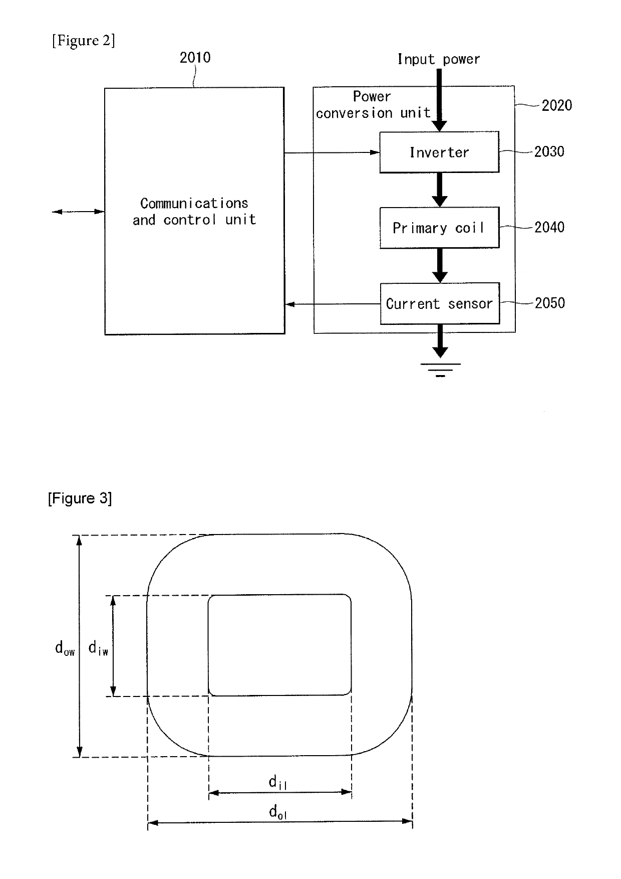
TABLE 1ParameterSymbolValueOuter lengthdol51.0 ± 0.5 mmInner lengthdil27.5 ± 0.5 mmOuter Widthdow43.0 ± 0.5 mmInner Widthdiw19.5 ± 0.5 mmThicknessdc 1.5 ± 0.5...

second embodiment

[0062]Next, the design dimensions of a transmitting coil according to the present invention are as follows.[0063]1 layer of coil with 12 turns which consists of D0.08 105 strands of Litz wire or equivalent wire[0064]Size: 50.0 mm in outer length (width), 20.0 mm in inner length (width)[0065]Shape of Shield Material: a minimum 2.5 mm margin from the outer edge of the coil[0066]Thickness of shield material: a minimum of 1.5 mm[0067]Thickness of Coil and Shield Material Assembly: 3 mm or less[0068]Self Inductance (@1V, 100 kHz): 10.0 μH[0069]AC Resistance (@1V, 100 kHz):

[0070]The design dimensions of the coil according to the second embodiment will be summed up in the following Tables 3.

[0071]Table 3 shows parameters such as the size, thickness, number of turns, etc. of the transmitting coil. In the second embodiment, however, the characteristics of the transmitting coil attached to the shield material are the same as the ones shown in Table 2.

TABLE 3ParameterSymbolValueOuter lengthdo...


PUM


Abstract

A wireless power transfer device includes an inverter configured to convert DC input to an AC waveform that drives a resonant circuit, a primary coil configured to generate a magnetic field, a shield material placed below the primary coil, a current sensor configured to monitor current in the primary coil, and a communications and control unit configured to communicate with a wireless power receiver device and control power transfer, wherein the primary coil consists of a single layer of which a number of turns is 12, and consists of 105 strands Litz wire of which the diameter is 0.08 mm, wherein the shield material is at least 1.5 mm thick and extends at least 2.5 mm beyond the outside of the primary coil, and wherein the primary coil and the shield material has a self-inductance 10.0 μH.

Description

CROSS REFERENCE TO RELATED APPLICATIONS[0001]This application is a Continuation of U.S. patent application Ser. No. 15 / 123,836, filed on Sep. 6, 2016, which was filed as the National Phase of PCT International Application No. PCT / KR2015 / 002147, filed on Mar. 5, 2015, which claims priority under 35 U.S.C. 119(e) to U.S. Provisional Application No. 61 / 949,258, filed on Mar. 7, 2014, all of which are hereby expressly incorporated by reference into the present application.BACKGROUND OF THE INVENTIONTechnical Field[0002]The present invention relates to a wireless power transmission device and method, and more particularly, to a wireless power transmission device and method which support both a low-power reception device and a medium-power reception device and properly transmit low power or medium power to each power reception device.Background Art[0003]Contactless wireless charging is an energy transfer method that electromagnetically transfers energy without wires, as opposed to the exi...

Claims


Application Information

Patent Timeline
Patent Type & Authority Applications(United States)
IPC IPC(8): H02J50/10H02J50/70H02J50/80H02J50/12H02J50/60
CPCH02J50/10H02J50/70H02J50/80H02J50/12H02J50/60H02J50/40H02J50/90
Inventor LEE, JAESUNGPARK, JINMOOLEE, JIHYUN
Owner LG ELECTRONICS INC
Why Eureka
Try Eureka