Method and apparatus for reducing space charge in an ion trap

a technology of space charge and ion trap, which is applied in the direction of mass spectrometer, isotope separation, particle separator tubes, etc., can solve the problems of increasing the need for handling the associated increase in space charge, the distortion of the mass spectrum obtained from the trapped ions becomes distorted, and the need for handling the increased space charge becomes more critical. , to achieve the effect of reducing space charge interferen

Inactive Publication Date: 2010-12-07
DH TECH DEVMENT PTE
View PDF10 Cites 7 Cited by
  • Summary
  • Abstract
  • Description
  • Claims
  • Application Information

AI Technical Summary

Benefits of technology

[0003]As mass spectrometry methods continue to evolve, one recent approach to improve analytical efficiency, with improved resolution, has been to develop brighter ion sources to improve the sensitivity. Yet, as brighter ion sources are created and their use becomes more widespread, the need for handling the associated increase in space charge grows more critical. Some approaches that have been employed to avoid such space charge effects include minimizing the fill time of the ion trap, and / or reducing the duty cycle of the ion beam from the source by modulating the potential to an ion optic upstream of the ion trap, i.e. pulsing or defocusing the ion optic. However, none of these is a solution that permits efficient analysis in every case. As a result, it would be advantageous to provide additional or alternative methods and apparatus for addressing ion trap space charge.
[0005]Mass spectrometry apparatus having (1) a first quadrupole, an exit lens, and a linear ion trap disposed between the first quadrupole and the exit lens, the linear ion trap having a well-modulator quadrupole containing at least two differently potentiated zones, defining at least two different sectors of the linear ion trap such that the linear ion trap is capable of being operated to form potential wells, alternately or simultaneously, in at least two different sectors of the linear ion trap, the sectors including a proximal sector nearer the first quadrupole and a distal sector nearer the exit lens, wherein the linear ion trap is capable of operation whereby an ion population can be loaded from the first quadrupole into a well formed in the distal sector and, by manipulation of the potentials of differently potentiated zones of the well-modulator quadrupole, some of those ions can be transferred back to the first quadrupole by passage through a well formed in the proximal sector, the proximal sector well retaining a fraction of those ions, thereby preventing overfilling of the linear ion trap. See, e.g., FIGS. 3A-3D.
[0008](2) raising the potential of the linear ion trap to a level higher than the potential of the first quadrupole, and decreasing the potential of the proximal sector to form a proximal sector well defined in part by a higher potential wall at its upstream end, and
[0009](3) raising the potential of the distal sector well to a level that is about the same as or greater than that of the wall, thereby transferring ions from the distal sector well to the first quadrupole and transferring a fraction of the ions from the distal sector well to the proximal sector well.
[0021]Such methods further involving (V) scanning the fraction of ions of step (IV) out of the linear ion trap and detecting ions released therefrom, the method thereby substantially reducing space charge interference in the detection of an ion of interest from the released ions.
[0024]Such methods further involving (V) scanning the fraction of ions of step (IV) out of the linear ion trap and detecting ions released therefrom, the method thereby substantially reducing space charge interference in the detection of an ion of interest from the released ions.

Problems solved by technology

One issue that is common to all ion trapping systems is excess space charge, resulting from relative overfilling of the ion trap, and the interference that is exhibited as a result of space charge, whereby the mass spectrum obtained from the trapped ions becomes distorted.
Such distortion particularly pronounced in some trap scan techniques.
Yet, as brighter ion sources are created and their use becomes more widespread, the need for handling the associated increase in space charge grows more critical.
However, none of these is a solution that permits efficient analysis in every case.

Method used


Image

  • Method and apparatus for reducing space charge in an ion trap
  • Method and apparatus for reducing space charge in an ion trap
  • Method and apparatus for reducing space charge in an ion trap

Examples


examples

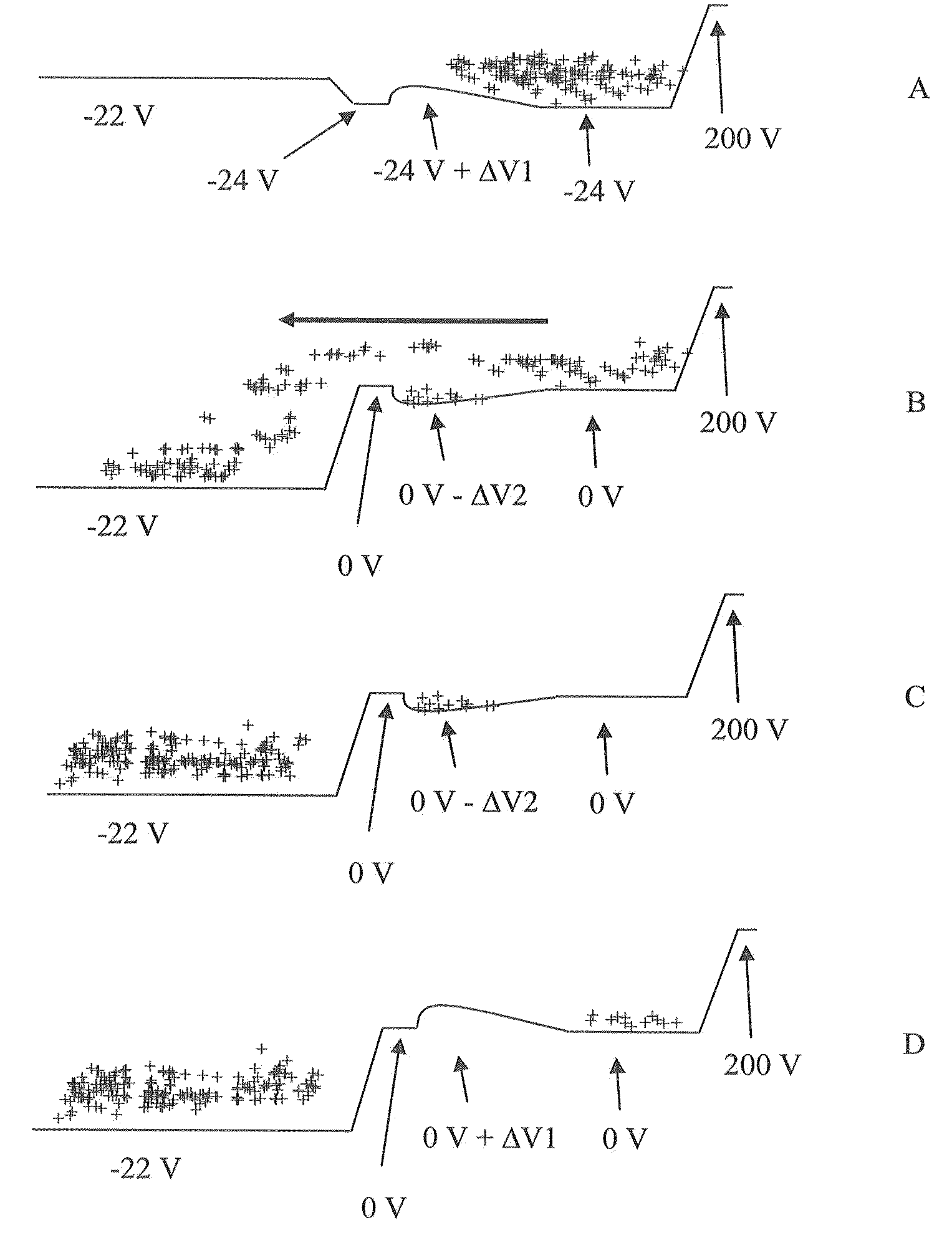
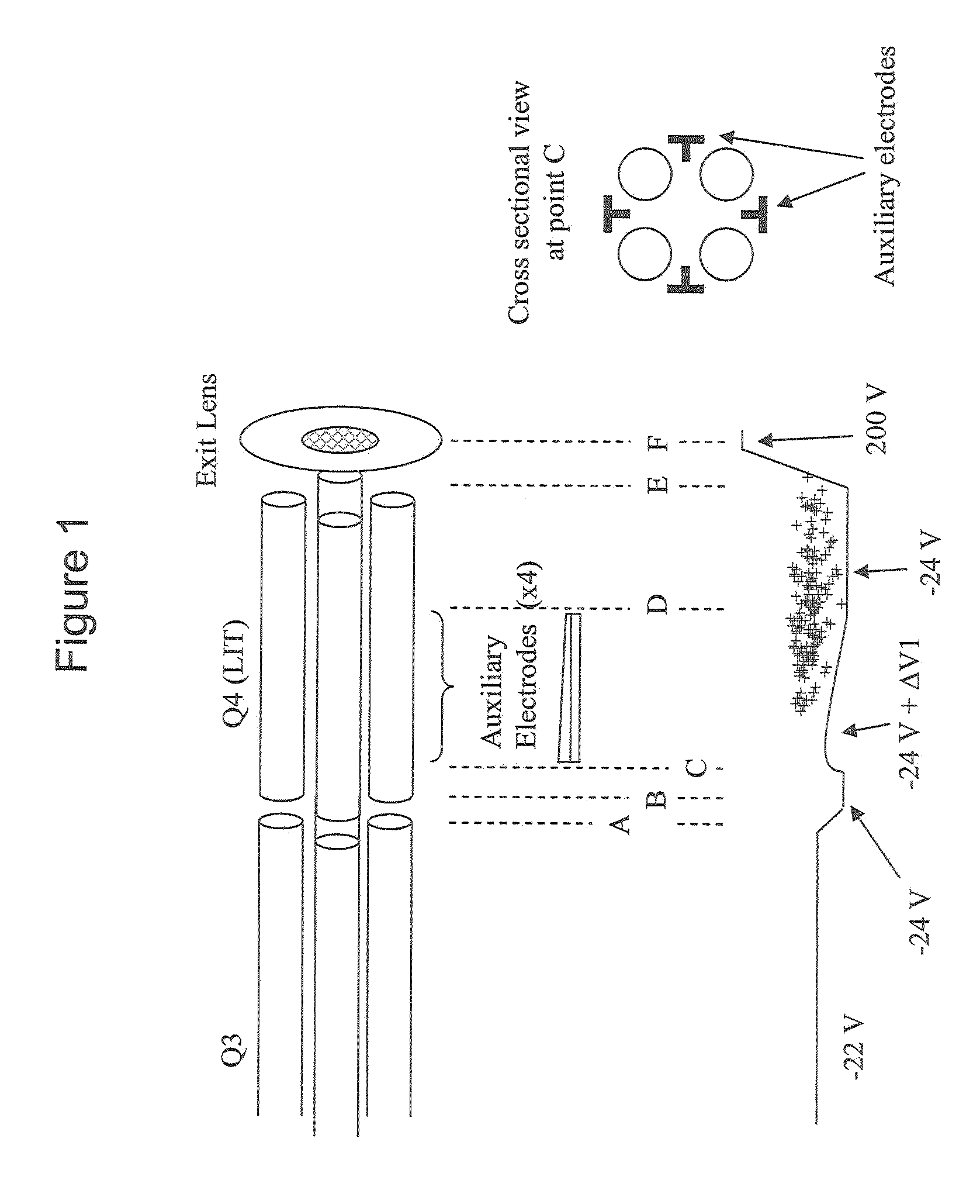
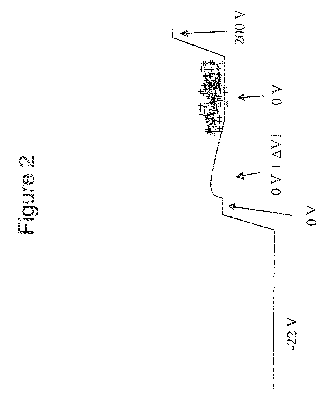
[0071]Experimental. All experiments are carried out on a modified 4000 Q Trap (mass spectrometry system, from Applied Biosystems, Foster City, Calif., USA), using a short linear ion trap (SLIT) situated between the Q3 rod-set and the exit lens. This is illustrated in FIG. 1, along with the potentials applied to each optic during the fill step. The potential applied to the auxiliary electrode is 200 V during this step and produces an additional potential of ΔV1 along the axis of the SLIT. The ions are denoted by the +'s. During the filling of the SLIT, the potentials along the length of the ion path are adjusted to admit as many ions as possible into the SLIT. After the SLIT has been filled, the rod offset on the SLIT is raised to 0 V while the potential on Q3 is left low; see FIG. 2. This prevents energetic ions that are remaining in Q3 from transferring into the SLIT during the scanning out step. The ions are scanned out of the SLIT using the technique of mass selective axial eject...


PUM


Abstract

Ion trap apparatus and methods for efficiently addressing the effects of charge space caused by ion trap overfilling, useful in linear ion traps of mass spectrometers.

Description

CROSS-REFERENCE TO RELATED APPLICATIONS[0001]This application claims the benefit of U.S. Provisional Application No. 61 / 017,203 filed on Dec. 28, 2007. The entire disclosure of the above application is incorporated herein by reference.INTRODUCTION AND SUMMARY[0002]Ion traps, such as those employed in mass spectrometers, are widely used in analytical techniques. One issue that is common to all ion trapping systems is excess space charge, resulting from relative overfilling of the ion trap, and the interference that is exhibited as a result of space charge, whereby the mass spectrum obtained from the trapped ions becomes distorted. Such distortion particularly pronounced in some trap scan techniques. In mass spectrometers, such as the 4000 Q Trap system (Applied Biosystems), the trap scan mode that suffers most from space charge is the enhanced mass spectrum (EMS) mode; and to a lesser extent space charge problems are also encountered in the enhanced resolution (ER) mode.[0003]As mass...

Claims


Application Information

Patent Timeline
Patent Type & Authority Patents(United States)
IPC IPC(8): H01J49/42
CPCH01J49/4225H01J49/4265
Inventor COLLINGS, BRUCE A.
Owner DH TECH DEVMENT PTE
Why Eureka
Try Eureka