Power monitoring photo eye controller

a technology of power monitoring and eye controller, which is applied in the direction of instruments, wing accessories, and individual entry/exit registers, can solve the problems of inconvenient or impractical use of wired control or power supply lines, broken wires or inadvertent disconnection of control wiring, and inconvenient use of wired systems or electromechanical connections, etc., to achieve low battery maintenance, prolong battery life, and reduce installation time

Inactive Publication Date: 2011-01-11
MILLER EDGE
View PDF2 Cites 4 Cited by
  • Summary
  • Abstract
  • Description
  • Claims
  • Application Information

AI Technical Summary

Benefits of technology

[0016]The benefits of the invention include the lack of control wires to install the infrared transmitter or emitter means which reduces installation time while providing for low battery maintenance because of extended battery life incorporated into the design of the unit. The unit features beam alignment indicators to help a user install the transmitter and receiver unit and locate an optimal sighting line for defining the unobstructed path to be used for the infrared beam.

Problems solved by technology

In many instances it is inconvenient or impractical to use wired control or power supply lines between a detector and the photo emitter to supply power or otherwise integrate the system components.
Wired systems or electromechanical connections are frequently subject to potential failures from component fatigue induced by physical stress.
Since many systems use hard wired control systems to connect the sensors, part of the system vulnerability is the breaking of wires or the inadvertent disconnection of the control wiring during operation of the equipment or otherwise.
Systems deployed today utilizing batteries could fail if the battery is being depleted to transmit a low battery condition in a wireless control scenario.

Method used


Image

  • Power monitoring photo eye controller
  • Power monitoring photo eye controller
  • Power monitoring photo eye controller

Examples


Embodiment Construction

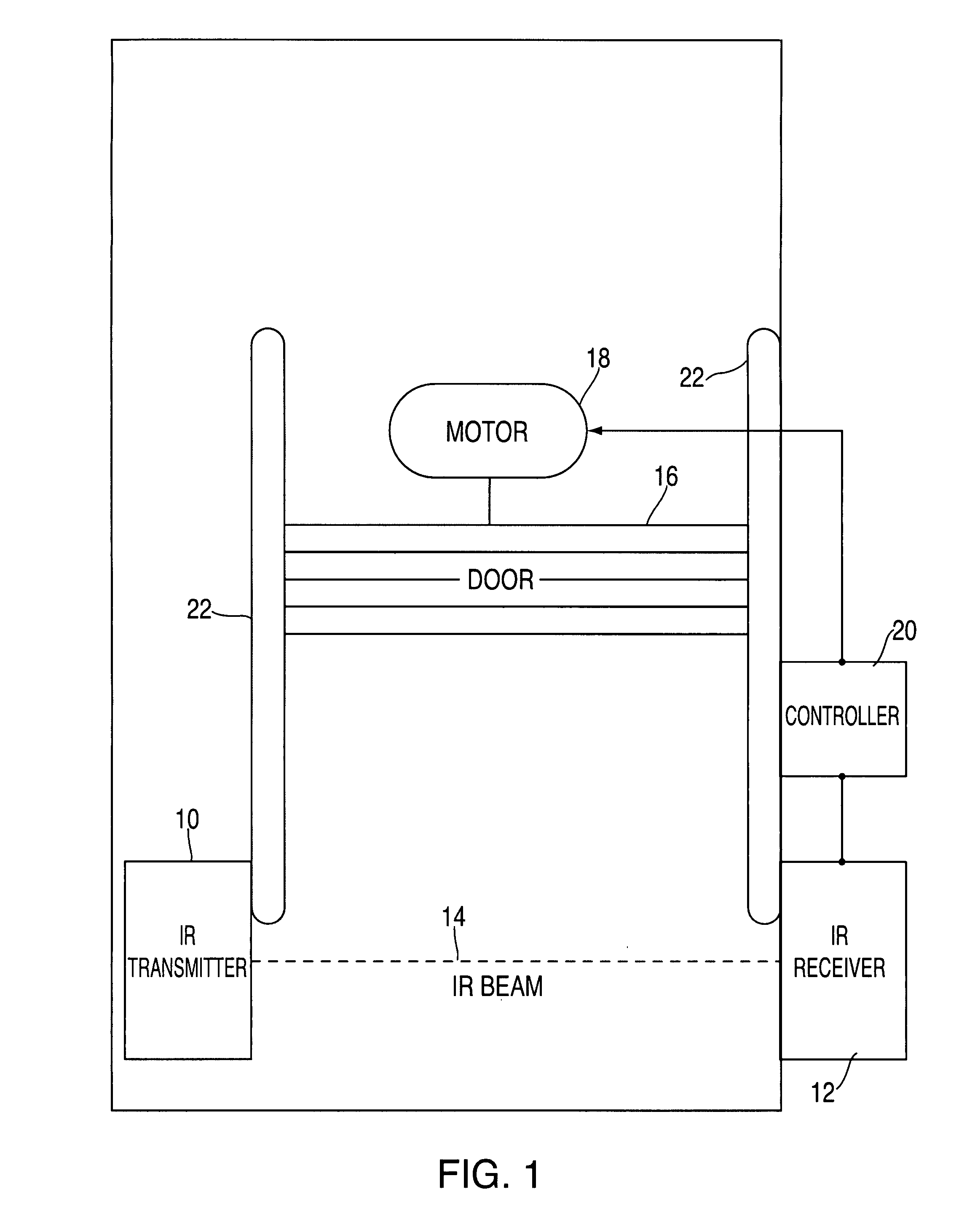
[0022]The invention will now be described with reference to the various figures wherein like numbers refer to like parts. FIG. 1 is a schematic representation of the invention showing an application as a safety system for a typical motorized overhead garage door opener. A typical system in which the preferred embodiment of the invention is applied includes a movable overhead door 16 which moves vertically riding on door tracks 22. Typically motor 18 is operatively connected to door 16 providing motion to open and close door 16 upon command. Typically in motor 18, a controller 20 is either integrated into the motor control systems found in present day electric motors or is contained separately in a remotely located control system attached, for example, on a wall or near a manual activator button such as to command opening and closing door 16.

[0023]In the present invention it is desired to monitor obstructions in the path of door 16 utilizing an infrared (“IR”) beam 14. Infrared beam ...


PUM


Abstract

A wireless, automatic door obstruction detection system for protecting a motorized door or gate by signaling various hazardous conditions and reacting to said conditions by signaling control means. The invention utilizes wireless infrared emitter, receiver and controller apparatus. Infrared pulse timing data is sent as pulse repetition rate changes depending upon battery condition. In a preferred embodiment of the invention, the photoelectric transmitter emits timed pulse groups to present control information differentiating between a good battery and a low battery condition in the wireless transmitter. A wireless photoelectric transmitter extends the time period between pulse groups to indicate a low battery condition. A low battery condition signaling thereby presents a low power drain condition allowing for an extended period of low battery condition signaling.

Description

BACKGROUND OF THE INVENTION[0001]1. Field of the Invention[0002]The present invention relates generally to automatic door and gate systems, and more particularly to automatic door safety systems which detect hazardous conditions, obstructions and adjusts operating controls accordingly.[0003]2. Related Art[0004]Systems which control gates and motorized doors have been well-developed in commercial and residential applications. Systems which control doors and gates typically comprise a motorized system which opens and closes the gate or the door upon command such as when a switch is activated or a motion detector senses the arrival of a vehicle in a predetermined area. Such systems often include additional devices and apparatus which assist in the utility or safety of the systems so disposed.[0005]The ubiquitous form of automatic door systems as for home garages or warehouse entry and exit doors or large overhead doors for commercial buildings usually have a transmitter and receiver al...

Claims


Application Information

Patent Timeline
Patent Type & Authority Patents(United States)
IPC IPC(8): H04B10/04H04B10/00
CPCG08C23/04G07C2009/00928E05Y2900/106E05F15/43
Inventor SAO, VINAYTEJESWI, KRISHNARAJ N.LEIGH, GARYMILLER, BEARGE
Owner MILLER EDGE
Why Eureka
Try Eureka