Fastener driving tool
a technology of fastener and driving tool, which is applied in the direction of manufacturing tools, nailing tools, stapling tools, etc., can solve the problems that the fastener driving tool may become bulky in a different direction, and achieve the effects of high resistance, high strength and high acceleration of the plunger
- Summary
- Abstract
- Description
- Claims
- Application Information
AI Technical Summary
Benefits of technology
Problems solved by technology
Method used
Image
Examples
first embodiment
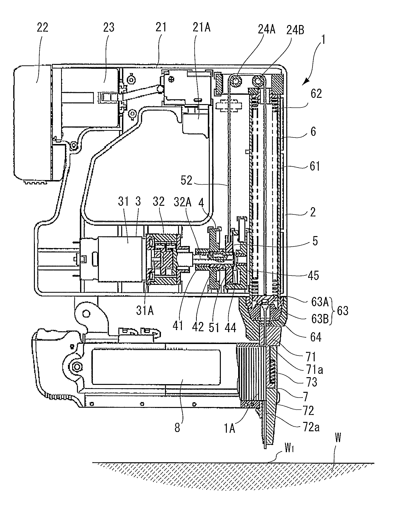
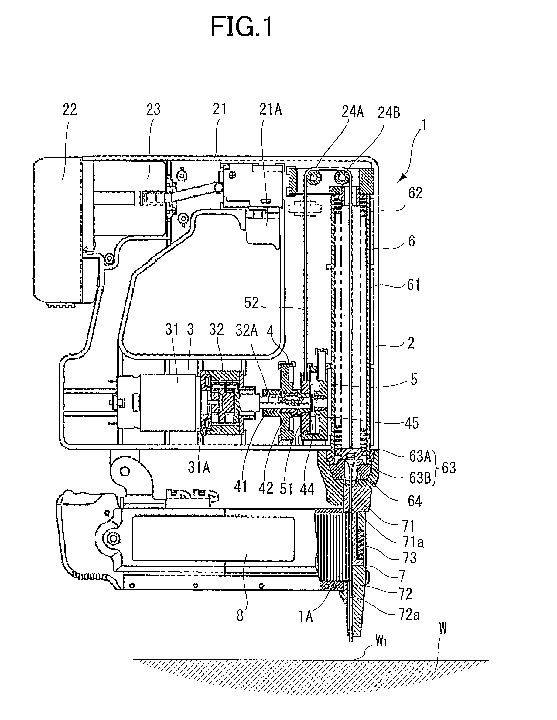
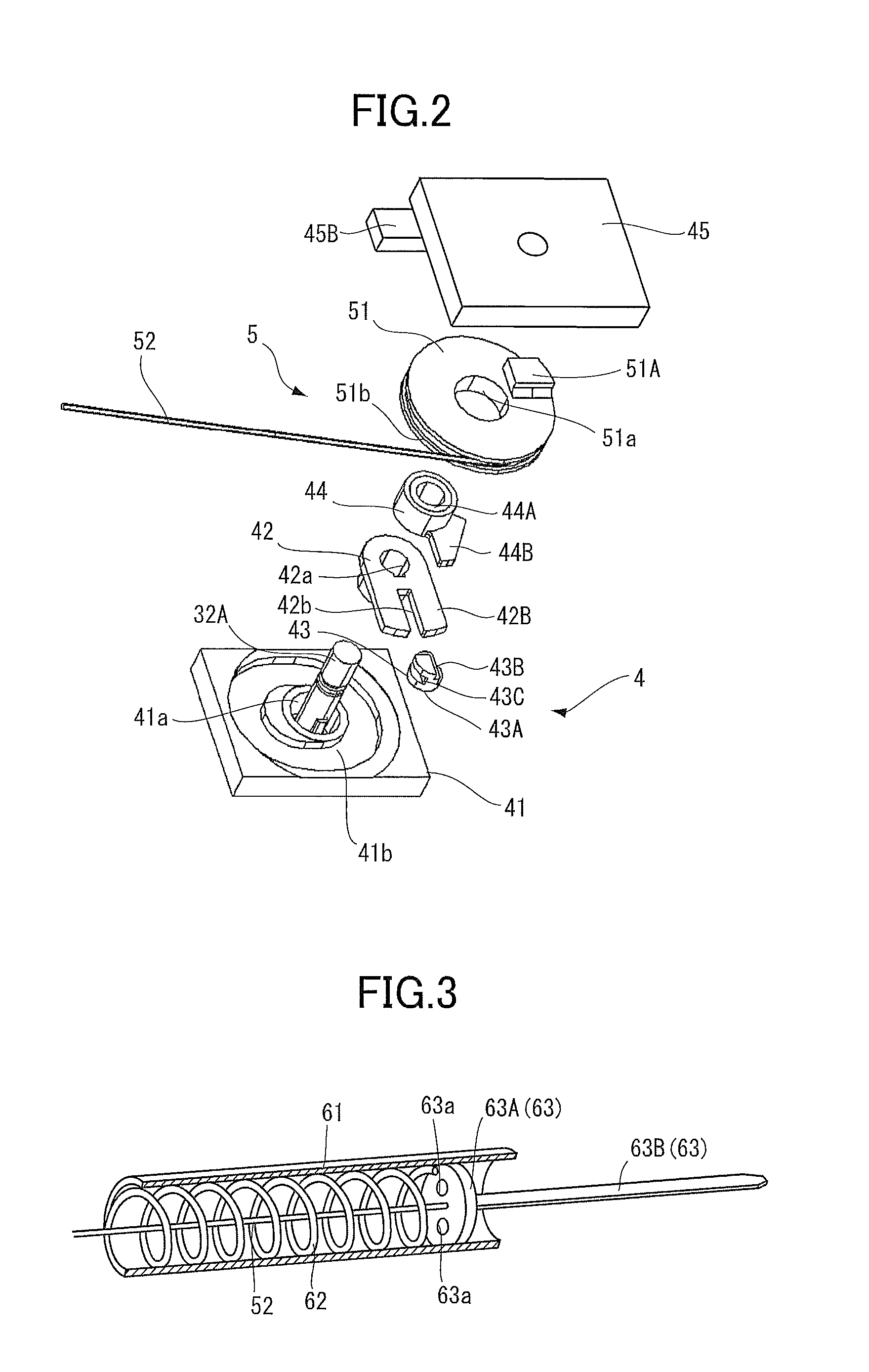
[0165]A fastener driving tool according to the present invention will be described with reference to FIGS. 1 through 5C. The fastener driving tool shown in FIG. 1 is an electrically-operated type nail gun 1 where a fastener such as a nail 1A is adapted to be driven into a workpiece W such as a wood and a gypsum plaster board. The nail gun 1 mainly includes a housing 2, a driving portion 3, a clutch mechanism 4, a transmission portion 5, a coil spring portion 6, a nose portion 7, and a magazine 8. Hereinafter, a direction in which a plunger 63 described later moves away from a damper 64 described later will be described as an upper direction, and a direction in which the plunger 63 is urged by a coil spring 62 described later to strike the nail 1A will be described as a lower direction.
[0166]The housing 2 is made from resin such as nylon and polycarbonate and accommodates the driving portion 3 and the like. A handle 21 is provided on an upper section of the housing 2 and is provided ...
second embodiment
[0225]Further, as shown in FIG. 17, a plunger 463 according to a modification to the second embodiment includes an urging main body 463A, a blade 463B and a pin 463F. The urging main body 463A and the blade 463B are connected by the pin 463F. The urging main body 463A is formed with a through-hole 463b through which the pin 463F is inserted. As shown in FIG. 18, the blade 463B is formed with a through-hole 463c through which the pin 463F is inserted. Accordingly, the pin 463F is inserted into the through-holes 463b and 463c in a state that the blade 463B is attached to the urging main body 463A, thereby fixing the blade 463B with the urging main body 463A. Therefore, the blade 463B can be easily replaced by a new blade by pulling the pin 463F from the through-holes 463b and 463c, if the blade 463B is damaged such as bending.
[0226]Further, as shown in FIGS. 17 and 19, the retained portion 252A may be directly retained by the retaining portion 263C.
[0227]Further, a buffer mechanism (t...
PUM
 Abstract
Description
Claims
Application Information
 - R&D
- Intellectual Property
- Life Sciences
- Materials
- Tech Scout
- Unparalleled Data Quality
- Higher Quality Content
- 60% Fewer Hallucinations
Browse by: Latest US Patents, China's latest patents, Technical Efficacy Thesaurus, Application Domain, Technology Topic, Popular Technical Reports.
© 2025 PatSnap. All rights reserved.Legal|Privacy policy|Modern Slavery Act Transparency Statement|Sitemap|About US| Contact US: help@patsnap.com


