
Fastener driving tool

a technology of fastener and driving tool, which is applied in the direction of manufacturing tools, nailing tools, stapling tools, etc., can solve the problems that the fastener driving tool may become bulky in a different direction, and achieve the effects of high resistance, high strength and high acceleration of the plunger

Inactive Publication Date: 2010-04-29
HITACHI KOKI CO LTD
View PDF30 Cites 7 Cited by
  • Summary
  • Abstract
  • Description
  • Claims
  • Application Information

AI Technical Summary

Benefits of technology

[0005]In view of the foregoing, it is an object of the present invention to provide a fastener driving tool having a compact and lightweight structure.
[0024]With this arrangement, excessive rotation of the drum in the housing can be prevented. Further, since the initial position for winding one of the wire and the sheet member is defined, a time period from a start timing to an end timing of the fastener driving operation can be stabilized.

Problems solved by technology

However, if the diameter of the rotation gear or the number of the rotation gears is increased, the fastener driving tool may become bulky in a direction other than a stroke direction of the plunger.

Method used


Image

  • Fastener driving tool
  • Fastener driving tool
  • Fastener driving tool

Examples


first embodiment

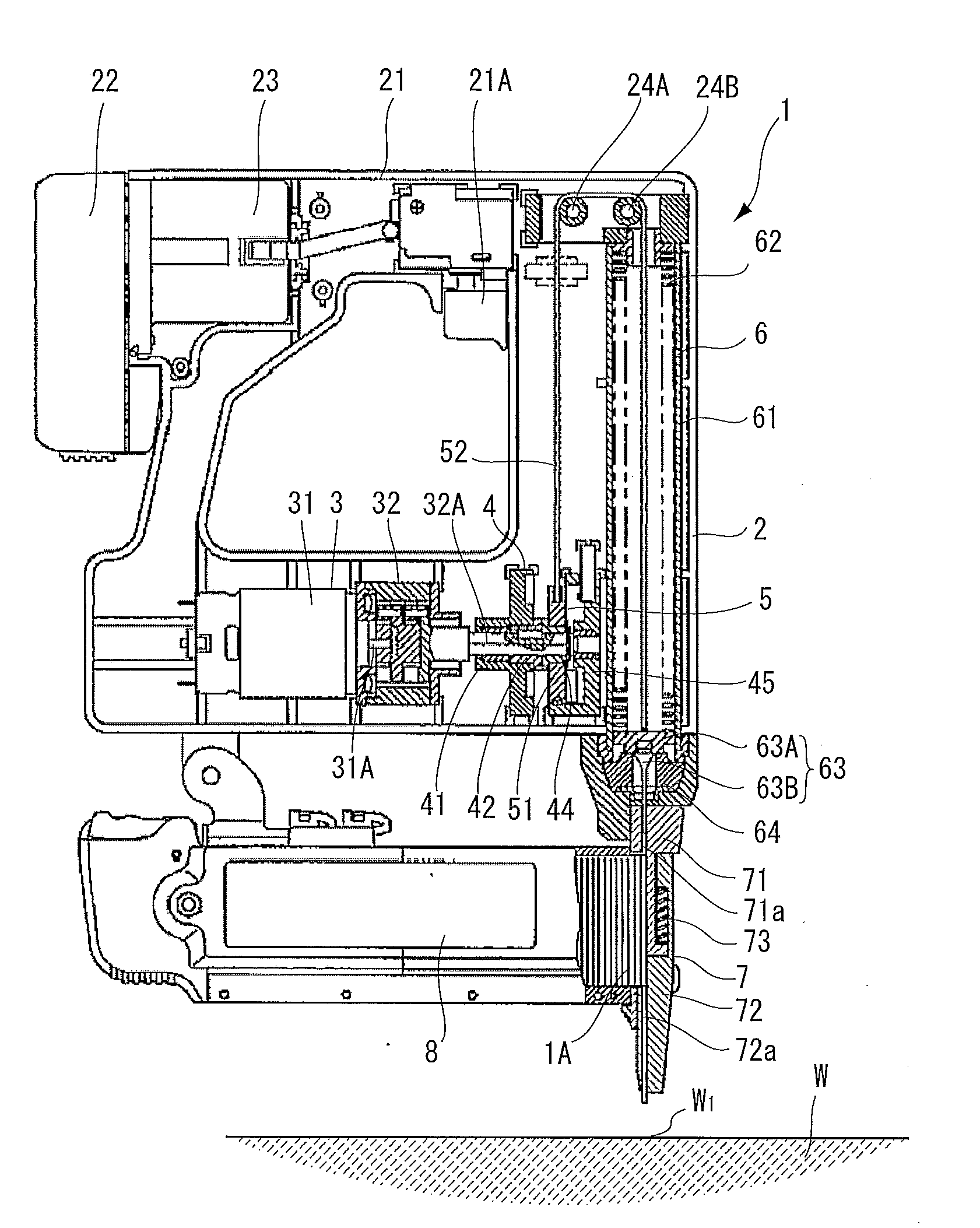
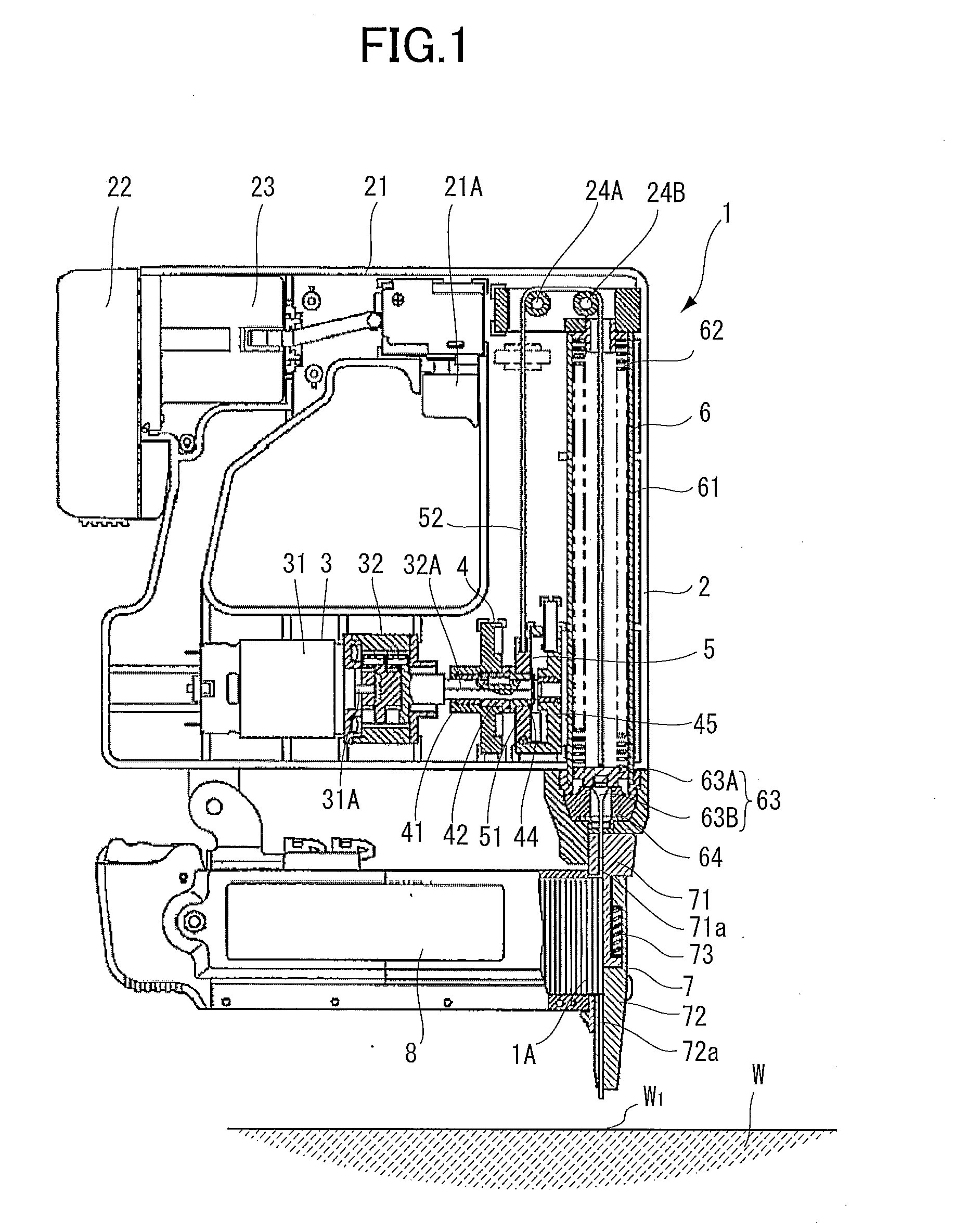
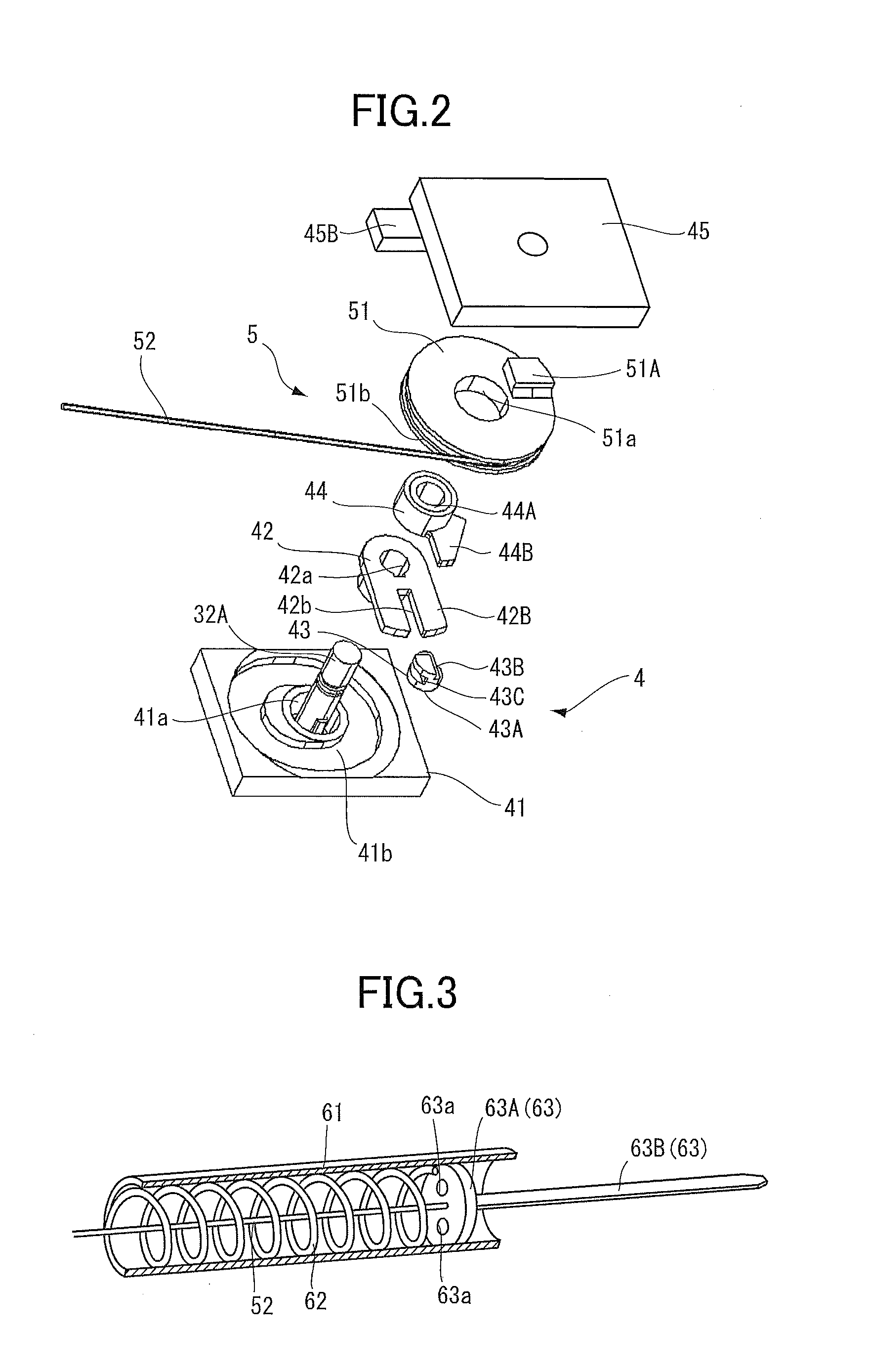
[0164]A fastener driving tool according to the present invention will be described with reference to FIGS. 1 through 5C. The fastener driving tool shown in FIG. 1 is an electrically-operated type nail gun 1 where a fastener such as a nail 1A is adapted to be driven into a workpiece W such as a wood and a gypsum plaster board. The nail gun 1 mainly includes a housing 2, a driving portion 3, a clutch mechanism 4, a transmission portion 5, a coil spring portion 6, a nose portion 7, and a magazine 8. Hereinafter, a direction in which a plunger 63 described later moves away from a damper 64 described later will be described as an upper direction, and a direction in which the plunger 63 is urged by a coil spring 62 described later to strike the nail 1A will be described as a lower direction.

[0165]The housing 2 is made from resin such as nylon and polycarbonate and accommodates the driving portion 3 and the like. A handle 21 is provided on an upper section of the housing 2 and is provided ...

second embodiment

[0224]Further, as shown in FIG. 17, a plunger 463 according to a modification to the second embodiment includes an urging main body 463A, a blade 463B and a pin 463F. The urging main body 463A and the blade 463B are connected by the pin 463F. The urging main body 463A is formed with a through-hole 463b through which the pin 463F is inserted. As shown in FIG. 18, the blade 463B is formed with a through-hole 463c through which the pin 463F is inserted. Accordingly, the pin 463F is inserted into the through-holes 463b and 463c in a state that the blade 463B is attached to the urging main body 463A, thereby fixing the blade 463B with the urging main body 463A. Therefore, the blade 463B can be easily replaced by a new blade by pulling the pin 463F from the through-holes 463b and 463c, if the blade 463B is damaged such as bending.

[0225]Further, as shown in FIGS. 17 and 19, the retained portion 252A may be directly retained by the retaining portion 263C.

[0226]Further, a buffer mechanism (t...


PUM


Abstract

A fastener driving tool includes a housing, a motor, a plunger, a spring, a drum, and one of a cable and a sheet member. The motor is provided in the housing. The plunger is provided in the housing for impacting a fastener in a fastener driving direction. The spring urges the plunger in the fastener driving direction. The drum is rotatably supported in the housing and is rotationally driven by the motor. The one of a cable and a sheet member is capable of being wound over the drum and has one end fixed to the drum and another end acting on the spring for transmitting a driving force of the motor to the spring. The spring is configured to accumulate a resilient energy therein for impacting the fastener by the plunger. The resilient energy of the spring is accumulated by forcible resilient deformation thereof as a result of winding of the one of the cable and the sheet member over the drum rotationally driven by the motor.

Description

TECHNICAL FIELD[0001]The present invention relates to a fastener driving tool, and more particularly, to an electrical fastener driving tool.BACKGROUND ART[0002]In a conventional fastener driving tool, a fastener such as a nail is adapted to be driven into a workpiece such as a wood and a gypsum plaster board by urging and accelerating a plunger using an urging force of a spring. Such fastener driving tool accumulates an resilient energy of the spring by a motor accommodated in the fastener driving tool.[0003]A coil spring can accumulate an resilient energy by expansion or compression. The expansion or compression of the coil spring is achieved by a motor, a reduction gear, a plunger and a plurality of rotation gears as described in Japanese Patent Publication No. H09-295283. Each of the plurality of the rotation gears has a driving pin that is fixed at a position separately from a rotation center of each rotation gear. The plunger has a plurality of protrusions. The plunger is push...

Claims


Application Information

Patent Timeline
IPC IPC(8): B25C1/06
CPCB25C1/06
Inventor TANIMOTO, HIDEYUKISAKABA, TOSHIHITOODA, HIROYUKINAKANO, YOSHIHIRO
Owner HITACHI KOKI CO LTD
Learn More