
Expandable intervertebral spacer and method of posterior insertion thereof

a technology of intervertebral spacers and spacers, which is applied in the field of intervertebral spacers and surgical methods for inserting intervertebral spacers, can solve the problems of further injury to other components of the spine, damage to nerve roots, etc., and achieve the effect of increasing the overall height and width of the spacer

Active Publication Date: 2013-03-12
GLOBUS MEDICAL INC
View PDF6 Cites 55 Cited by
  • Summary
  • Abstract
  • Description
  • Claims
  • Application Information

AI Technical Summary

Benefits of technology

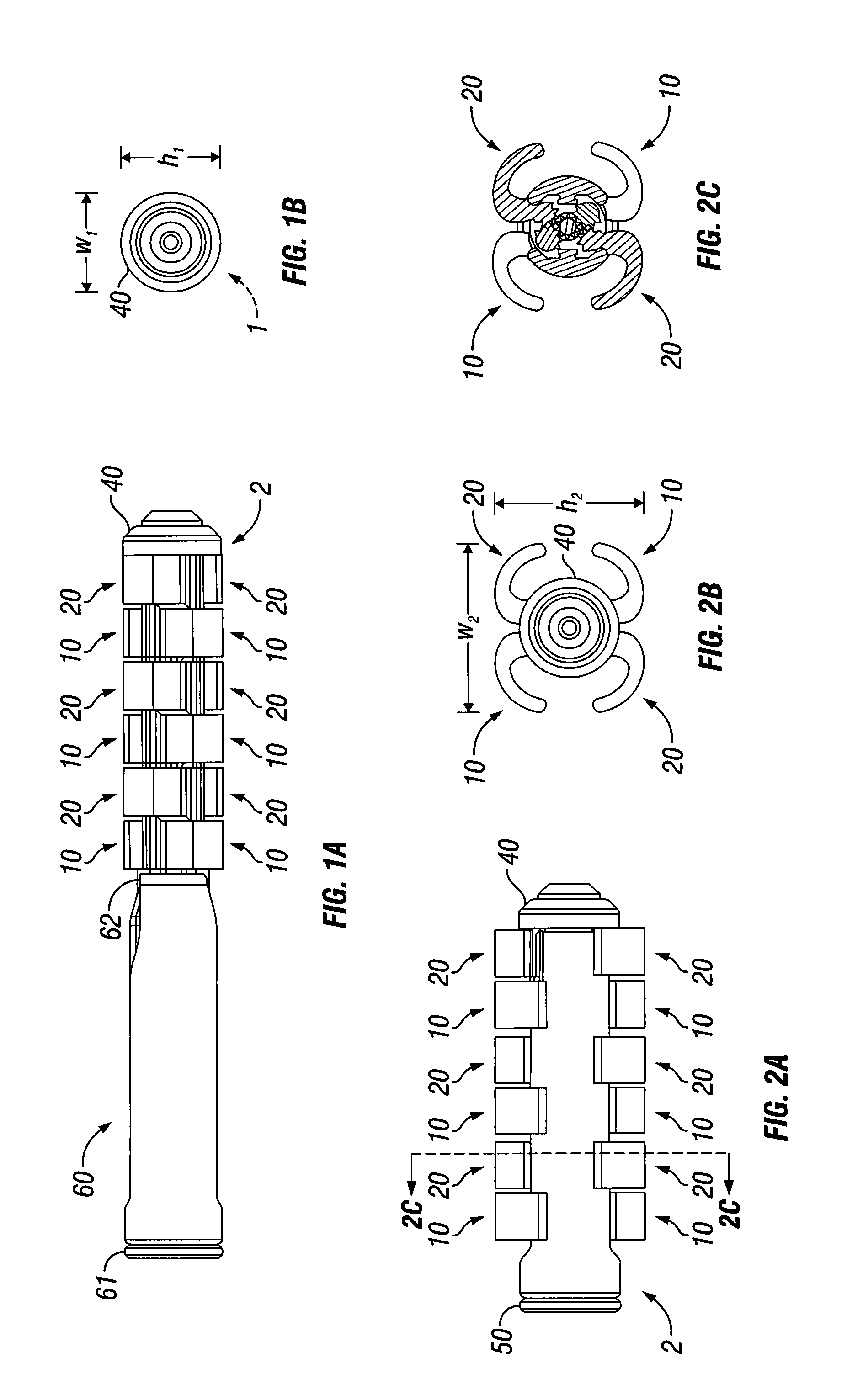
[0010]According to one aspect of the invention, an expandable intervertebral spacer for posterior approach to an intervertebral space without needing retraction of a nerve root is provided. The spacer has a body and at least one rotatable extension. The rotatable extension will be hereafter referred to as “arm”. The body has a width that is narrow enough to fit between the nerve roots at the posterior entrance to an intervertebral space. The arm or arms retract within the body when the spacer is being passed between the nerve roots. The arm or arms are then deployed once the body has passed between the nerve roots into the intervertebral space. The arm or arms increase the overall height and width of the spacer when the arm or arms are deployed. The overall height of the spacer is adjusted to stabilize the adjacent vertebrae relative to each other. The expanding overall width of the spacer provides a broader base upon which the vertebrae are stabilized.
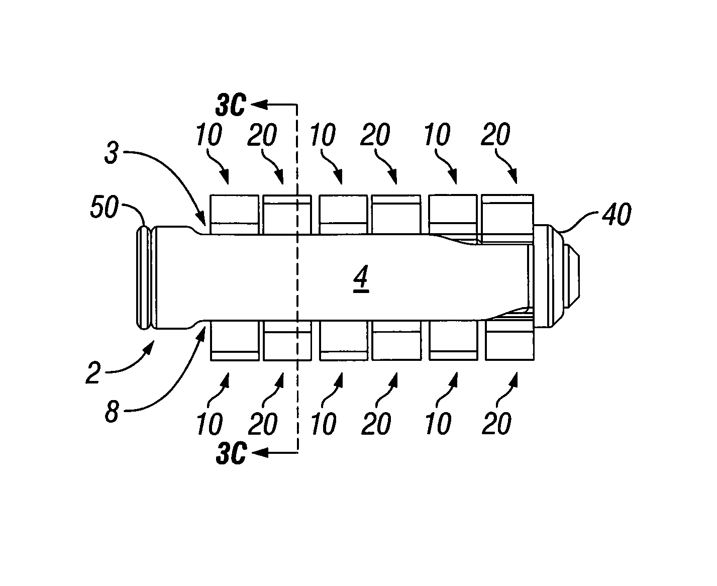
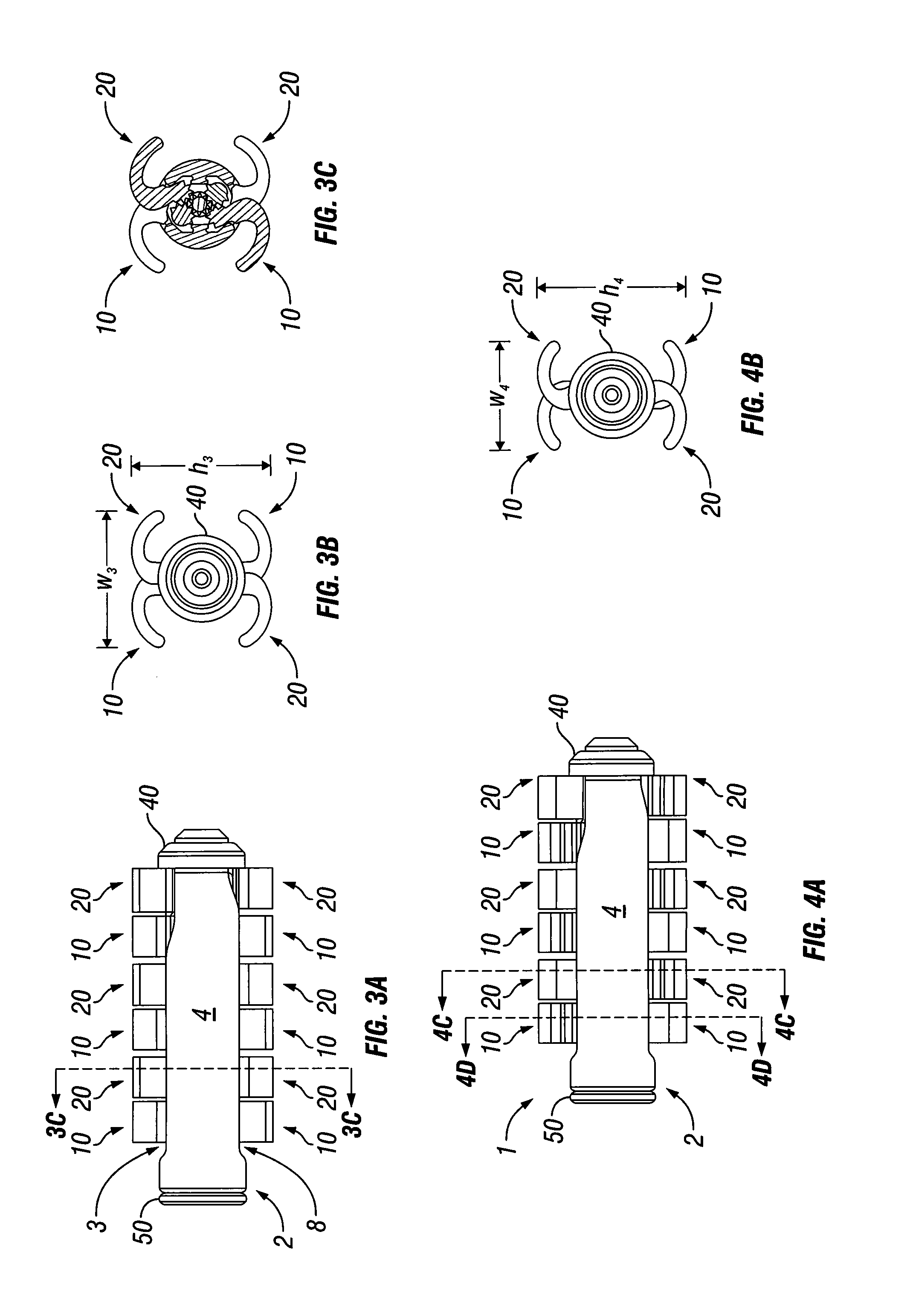
[0011]The spacer can include a plurality of arms. Deploying L-shaped arms from a superior and inferior surface of the body has been found by the inventors to be an advantageous way to provide a spacer that is narrow enough to fit between the nerve roots and that can expand after being inserted to be wide enough to provide a stabile base. Deploying the L-shaped arms also allows the spacer to expand enough vertically to fill the intervertebral space. Deploying some of the L-shaped arms by rotating them clockwise and others counterclockwise provides a useful way to expand the width of the spacer from both sides. Providing a spacer with arms that alternate between clockwise rotating arms and counterclockwise rotating arms along a depth (i.e. posterior to anterior) of the spacer has been found to provide a particularly stabile spacer. The number of arms along the depth of the spacer can be adjusted depending on the depth of the intervertebral space and the patient's anatomy. An implant with six pairs (i.e. superior and anterior) of arms has been found to provide a particularly stabile spacer.
[0013]It has been found to be advantageous to configure the arm so that it is short enough to be fully retracted within the body when retracted and long enough to extend beyond the body when deployed. To create this configuration, a furthest distance on the arm from the axis of rotation of the arm should be greater than the shortest distance from the axis of rotation to the perimeter of the body in the plane of rotation of the arm. A furthest distance on the arm from the axis of rotation should be less than a furthest distance on the perimeter of the body in a given plane of rotation of the arm.
[0019]The spacer is sized so that the overall width of the body with the arms retracted is narrower than a space between nerve roots blocking a posterior approach to an intervertebral space to be filled by the spacer. In this way, the spacer can be inserted into the intervertebral space by moving it between the nerve roots without needing to retract the nerve roots. Once the spacer is inserted into the intervertebral space, the arm or arms can be deployed to expand the overall width of the spacer to a width greater than the space between the nerve roots.
[0022]The depth (i.e. posterior to anterior length) of the space can approximate a depth of the intervertebral disc to be replaced. By having a depth that matches the depth of the disc being replaced, a stable connection between the spacer and the adjacent vertebrae can be established. In spacers having a longer depth, the number of arms along the length can be increased. In spacers having a shorter depth, the number of arms along the length can be decreased.
[0024]A method of using the spacer for stabilizing a first vertebra relative to a second vertebra via a posterior approach has the advantage that the nerve roots along with posterior of the intervertebral space do not need to be retracted. A first step of the method involves forming an incision to a posterior of an intervertebral space. The next step involves inserting an expandable intervertebral spacer in a retracted position into the intervertebral space. The intervertebral spacer has a height and width less than a distance between nerve root stems at the posterior of the intervertebral space. The next step is expanding a width and height of the expandable intervertebral spacer to a width wider than the distance between the nerve root stems and / or a height approximating a height of an intervertebral disc being replaced.

Problems solved by technology

Components of a motion segment that move out of position or become damaged can lead to serious pain and may lead to further injury to other components of the spine.
Underlying causes of structural changes in the motion segment unit leading to instability include trauma, degeneration, aging, disease, surgery, and the like.
There are several disadvantages to fusion, however.
When inserting a prosthesis into an intervertebral space via a posterior approach, the nerve roots can be damaged.

Method used


Image

  • Expandable intervertebral spacer and method of posterior insertion thereof
  • Expandable intervertebral spacer and method of posterior insertion thereof
  • Expandable intervertebral spacer and method of posterior insertion thereof

Examples


Embodiment Construction

[0042]Referring now to the figures of the drawing in detail, there is seen an expandable intervertebral spacer 1. The expandable intervertebral spacer 1 is typically inserted in a retracted state as shown in FIGS. 1A-1B into an intervertebral space. Once inserted into the intervertebral space, a width w and height h of the expandable intervertebral spacer 1 can be expanded as shown in FIGS. 2A-4F. The construction and operation of the expandable intervertebral spacer 1 are detailed below.

[0043]The expandable intervertebral spacer 1 includes a cylindrical body 2. The body 2 has a right side surface 4 and a left side surface 5. A superior slot 3 is formed in the body 2 at a superior position on the wall of the body 2. An inferior slot 8 is formed in the body 2 at an inferior position on the wall of the body 2. Arms 10, 20 deploy through the inferior and superior slots 3 and 8. As seen in FIG. 4D, the left and right side surfaces 4 and 5 have fins 6 and 7 formed on an inner surface of ...


PUM


Abstract

An expandable intervertebral spacer has a plurality of arms. The arms can be retracted or extended. The spacer has a width that is narrower than the width between the nerve roots near the posterior approach to an intervertebral space. Once inserted into the intervertebral space, the arms can be deployed. The deployed arms expand the height and width of the spacer. Once deployed, the spacer stabilizes two adjacent vertebrae. The arms are interconnected mechanically to deploy simultaneously.

Description

CROSS-REFERENCE TO RELATED APPLICATIONS[0001]This application claims priority to U.S. Provisional Application Ser. No. 61 / 307,659 filed on Feb. 24, 2010, which is incorporation herein in its entirety be reference.FIELD OF THE INVENTION[0002]The present disclosure generally relates to intervertebral spacers and surgical methods for inserting intervertebral spacers, in particular, insertion via a posterior approach.BACKGROUND OF THE INVENTION[0003]The spine includes a series of joints routinely called motion segment units, which are the smallest component of the spine that exhibits kinematic behavior characteristic of the entire spine. The motion segment unit is capable of flexion, extension, lateral bending, and translation. The components of each motion segment unit include two adjacent vertebrae and their apophyseal joints, the intervertebral disc, and the connecting ligamentous tissue. Each component of the motion segment unit contributes to the mechanical stability of the joint.[...

Claims


Application Information

Patent Timeline
Patent Type & Authority Patents(United States)
IPC IPC(8): A61F2/44
CPCA61F2/44A61F2/4611A61F2/446A61F2002/30224A61F2002/30233A61F2002/30482A61F2002/30523A61F2002/30545A61F2002/30556A61F2002/30579A61F2002/30594A61F2002/30598A61F2002/30889A61F2002/4627
Inventor WEIMAN, MARK
Owner GLOBUS MEDICAL INC
Learn More