Integrity of low bandwidth communications

a low-bandwidth communication and integrated technology, applied in frequency-division multiplex, instruments, coding, etc., can solve the problems of limited processing performance and available memory, and achieve the effect of reducing overhead, ensuring integrity of all packets, and ensuring fast check of integrity

Inactive Publication Date: 2013-03-12
GEMPLU
View PDF9 Cites 28 Cited by
  • Summary
  • Abstract
  • Description
  • Claims
  • Application Information

AI Technical Summary

Benefits of technology

[0023]This method is particularly advantageous for several reasons. In particular, the method only needs to transmit an integrity check per set rather than transmitting one integrity check per data packet. This reduces the bandwidth consumption accordingly.
[0027]Compared to an alternative method in which data packets of a set would be received, sorted in memory, and processed once the last packet is received the method of the invention would also be advantageous, in that once the last packet has been received, the integrity can be checked faster than in the alternative method since only the last packet would need to be processed. Therefore the time between the reception of the last packet and the validation of the integrity of all packets would be reduced.
[0028]According to a preferred embodiment, the method according to the invention is such that the integrity check value is included in the last packet sent by the sending communication device. It should be noted that the last packet sent by the sending communication device is not necessarily the last packet received by the receiving communication device (due for example to above-mentioned routing issues). This technique is advantageous as it avoids sending a separate packet, which would generate some overhead due not only to the packet header but also to the fact that the packet should be distinguished in order that the communication device identifies it as an integrity check value packet (rather than a packet carrying a regular payload). Sending the integrity check value in the last packet requires no overhead. The integrity check value can be appended just after the payload of the last packet. It may be stored in the space dedicated to the payload of the packet, which size would be increased accordingly (e.g. by updating a payload size field).

Problems solved by technology

Indeed the processor performance and the available memory might be limited, in particular in resource constrained communication devices such as smart cards.

Method used


Image

  • Integrity of low bandwidth communications
  • Integrity of low bandwidth communications
  • Integrity of low bandwidth communications

Examples


Embodiment Construction

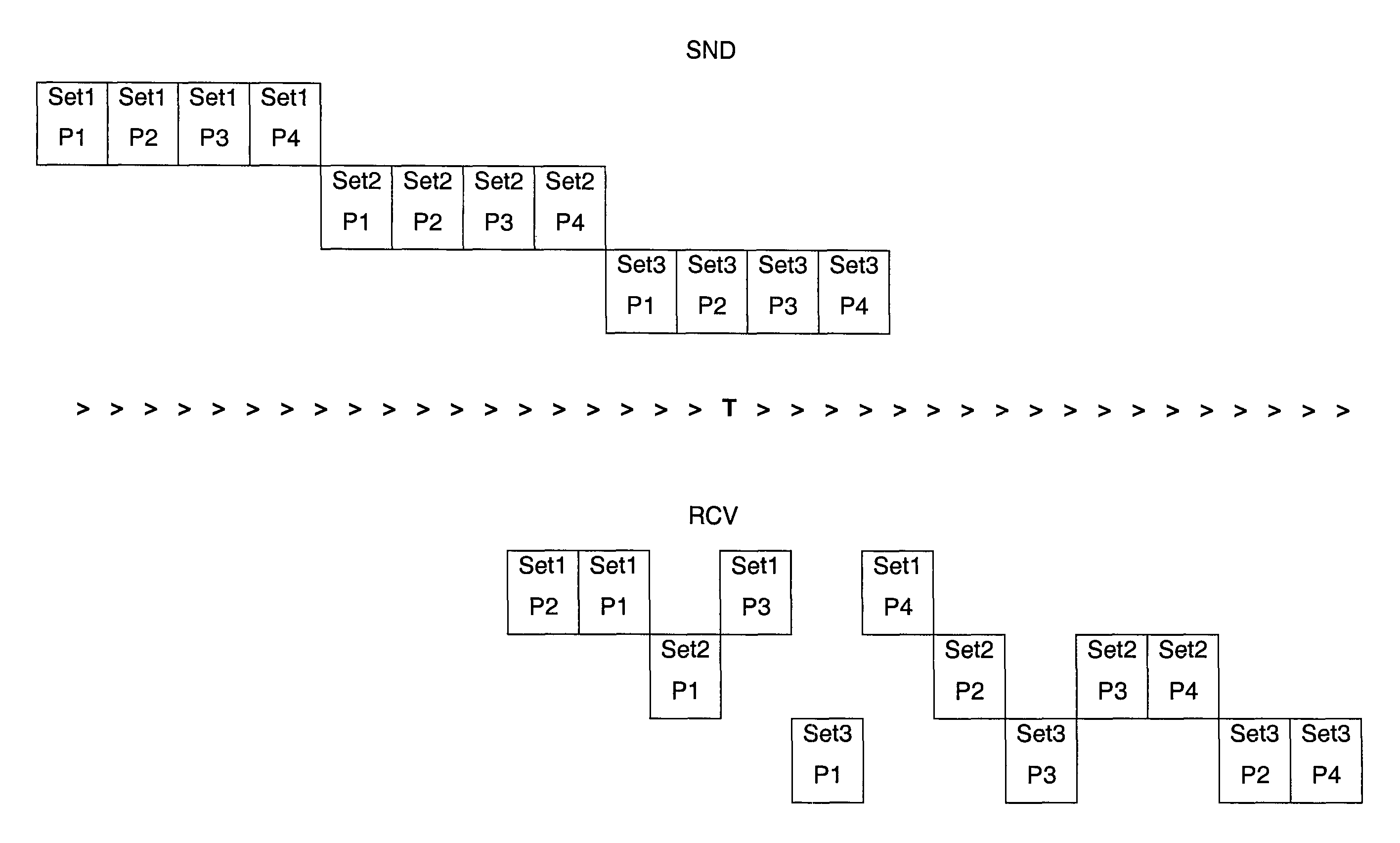
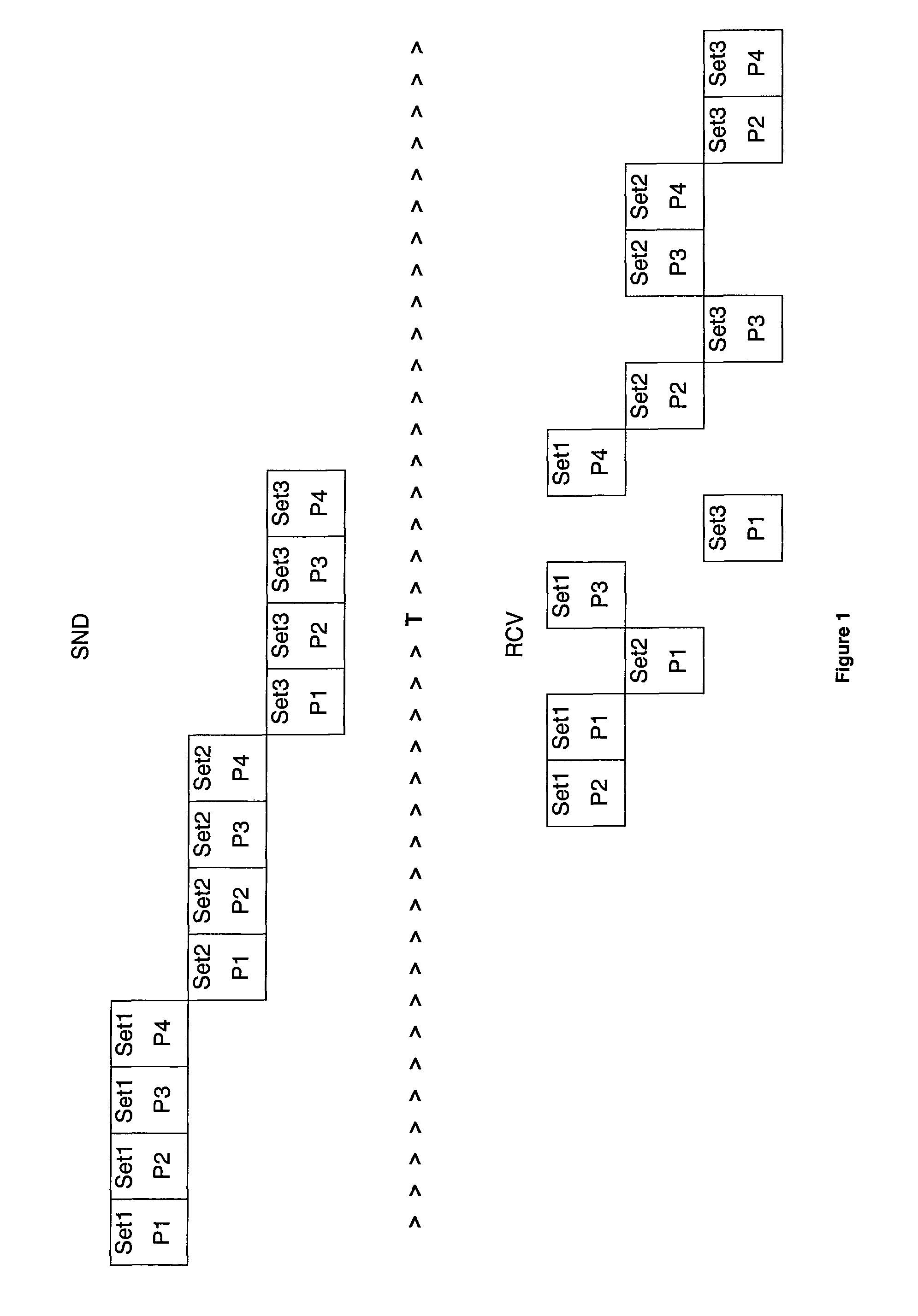
[0032]FIG. 1 illustrates one of the problems addressed by the invention.

[0033]The top of the diagram, identified by SND, depicts some sets of packets sent by the sending communication device, while the bottom of the diagram, identified by RCV, depicts the corresponding sets of packets received by the receiving communication device. T represents the time axis. As seen at the top of the diagram, three sets of four data packets are sent consecutively by a sending communication device. Set1 is sent first, then comes Set2 and at the end Set3. Within each set, packet P1 is sent first, then goes P2, then P3 and finally P4. Each set is represented on a different line for better legibility.

[0034]However, due for example to the fact that the network is such that packets traveling between two given points do not necessarily take the same path, the packets are not received in the order that they were sent.

[0035]FIG. 1 illustrates two issues. The first issue is linked to the fact that within a g...


PUM


Abstract

The invention relates to a method for checking the integrity of a set of data packets received by a receiving communication device from a sending communication device, the data packets of the set being received in unpredictable order. The invention also relates to a communication device implementing a method according to the invention, in particular to a smart card.

Description

BACKGROUND OF THE INVENTION[0001]1. Field of the Invention[0002]The invention relates to a method for checking the integrity of data communications. The invention is particularly relevant in the context of data communications between two communication devices connected via a low bandwidth network.[0003]The invention also relates to a communication device, in particular a smart card, embedding such a method.[0004]2. Description of the Related Art[0005]Communication devices are electronic devices comprising a communication interface. Examples of communication devices include smart cards, USB keys, dongles, Personal Digital Assistants (a.k.a PDAs), mobile phones, personal computers (a.k.a PCs), etc. Typically, such communication devices may be interconnected and communicate with others. For example, a mobile phone may comprise a game console and may allow its user to play games together with multiple other users of similar mobile phones, all mobile phones being connected to a game serv...

Claims


Application Information

Patent Timeline
Patent Type & Authority Patents(United States)
IPC IPC(8): G01R31/28G06F11/10H04J1/16
CPCH04L1/0061
Inventor SALGADO, STEPHANIEVIGILANT, DAVIDFUMAROLI, GUILLAUME
Owner GEMPLU
Why Eureka
Try Eureka