Hinge for bed frame assembly

a bed frame and assembly technology, applied in the field of bed frame assembly, can solve the problems of not being able to keep tarpaulins and other covers completely clean, carrying out extensive cleaning maintenance procedures, and maintaining the bed

Active Publication Date: 2013-03-19
HUNTLEIGH TECH LTD
View PDF39 Cites 14 Cited by
  • Summary
  • Abstract
  • Description
  • Claims
  • Application Information

AI Technical Summary

Benefits of technology

[0012]Preferably, the hinge assembly is electrically conductive such that a conductive path is provided through the assembly from one of the connecting members to the other. This enables the hinge to provide the electrical coupling between adjacent frame struts without the need for separate electrical wires.
[0014]Advantageously, the first and second connecting members are provided with a fastening element, in the preferred embodiment, an aperture able to receive an electrically conductive rivet or other electrically conductive fastener which would fasten together the hinge connectors to their respective frame strut, thereby providing an even more secure mechanical and electrical coupling.

Problems solved by technology

These hinges can cause a number of problems in maintaining the bed, particularly in a hospital or care home environment.
However, it is not possible to keep such tarpaulins and other covers totally clean, particularly in the current medical environments where “super-bugs” such as MRSA (Methicillin-Resistant Staphylococcus Aureus) and the like can quickly develop.
This has resulted in the need to carry out extensive cleaning maintenance procedures often taking a bed out of service for significant periods of time.
These wires, although performing an essential electrical function, add complexity to the manufacture and structure of the bed and represent another source of possible failure and areas for collection of dirt.

Method used


Image

  • Hinge for bed frame assembly
  • Hinge for bed frame assembly
  • Hinge for bed frame assembly

Examples


Embodiment Construction

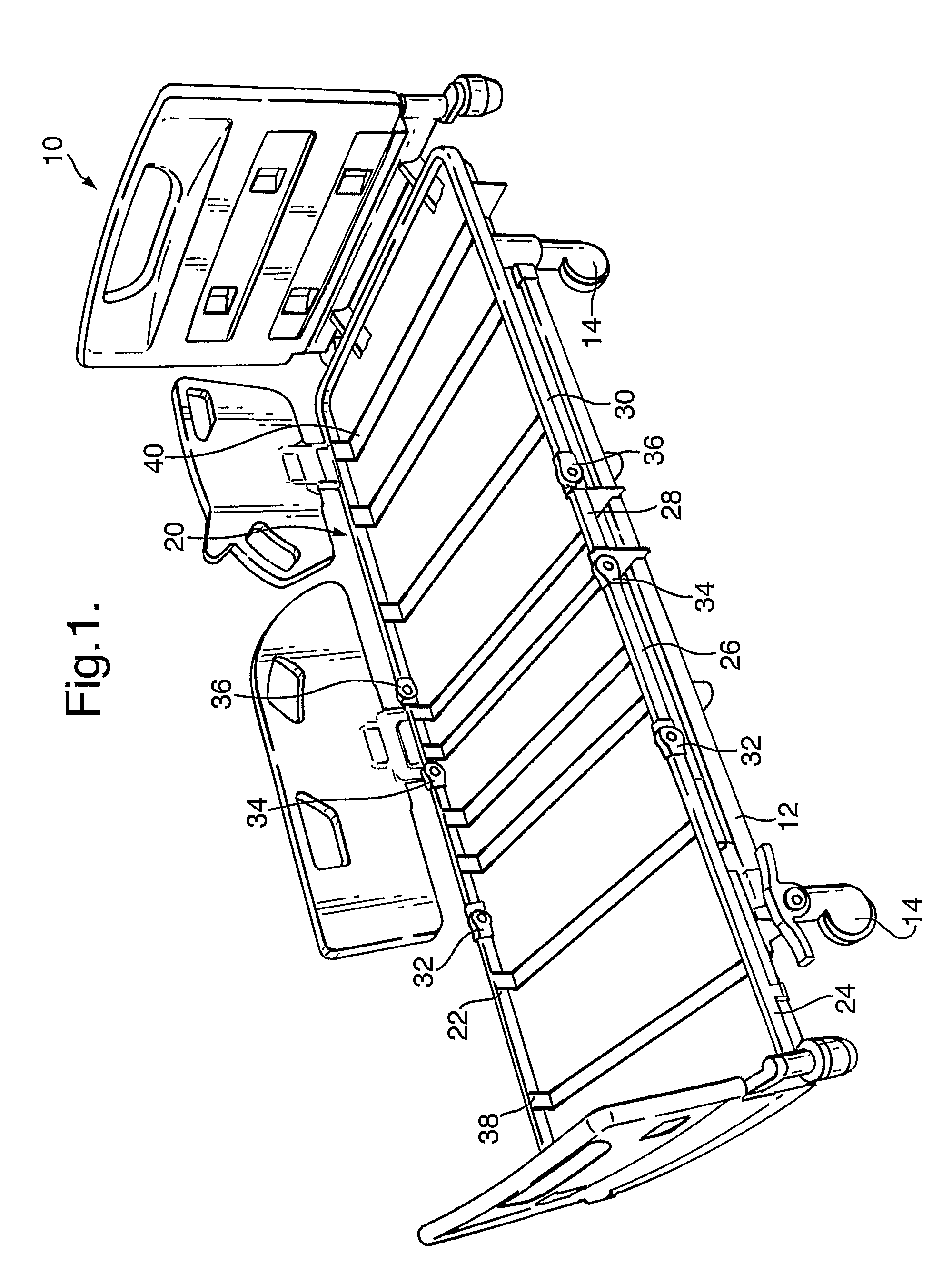
[0027]Referring to FIG. 1, there is shown a preferred embodiment of bed assembly 10 which includes a wheeled base 12 provided with four castors 14 of conventional type. Coupled to the base 12 is a bed platform 20 which can be raised and lowered relative to the base 12 and tilted by means of one or more electrical actuators (not shown), also of conventional type.

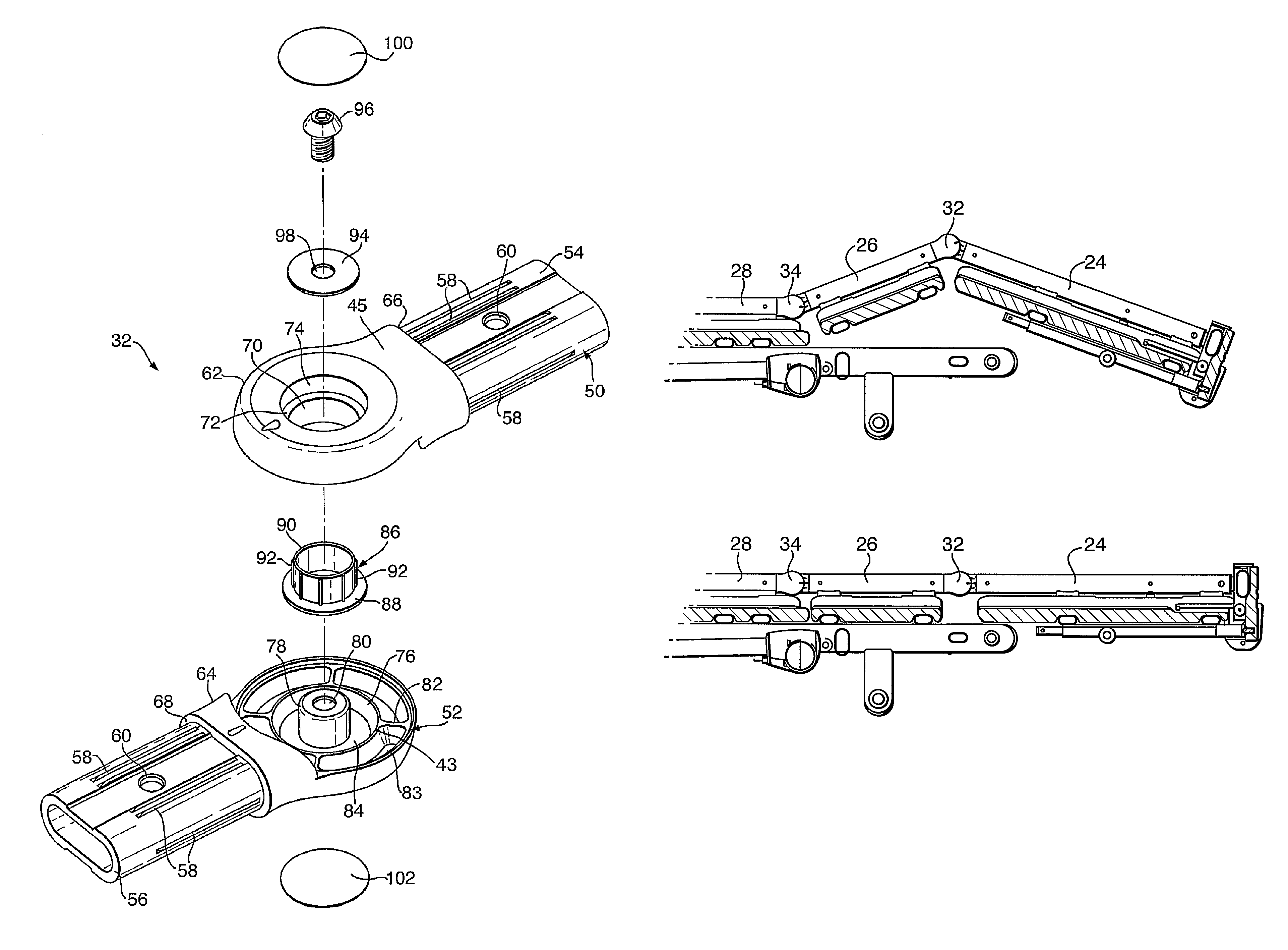
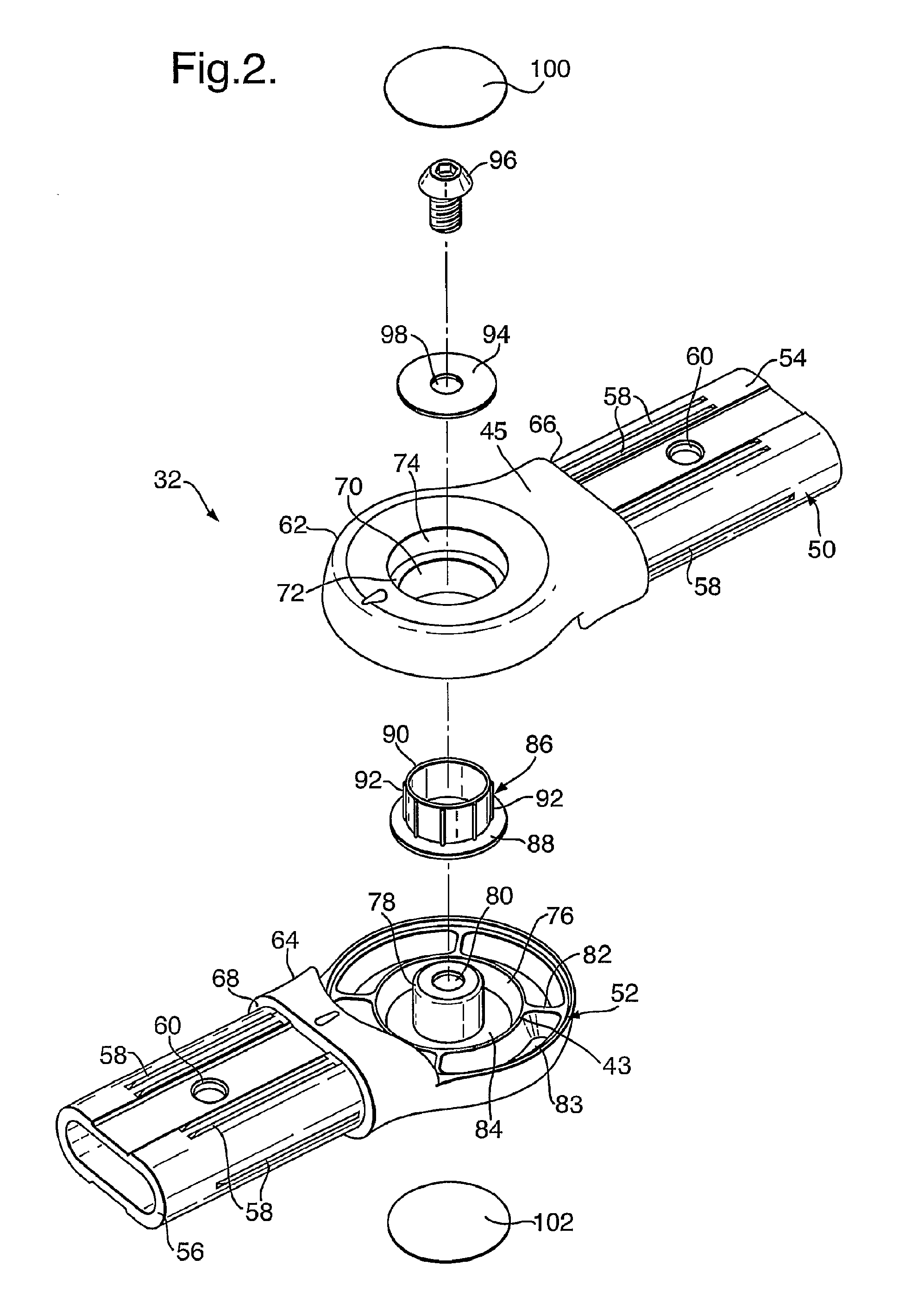
[0028]The platform 20 is provided with a frame 22 formed, in this embodiment, of four frame sections 24, 26, 28 and 30 which are coupled to one another by means of hinged joints 32, 34 and 36.

[0029]Each frame section 24-30 is provided with an upper frame member having substantially vertical inner side walls 38 and a plurality of depending transverse struts 40 to form a recessed support surface for supporting a plurality of mattress support panels, described in the applicant's co-pending British patent application numbers 0514926.5 and 0523184.0.

[0030]The hinges 32, 34 and 36 are provided in the upper frame members 24-30 and e...


PUM


Abstract

A hinge assembly (32-36) for a frame assembly (20) of for example, a hospital bed, has a smooth outer form which substantially conforms to the outer size of frame assembly struts to which it couples. The hinge assembly (32-36) has its components located internally and provides at least one reliable electrically conductive path therethrough so as to provide an electrical connection between frame struts (24-30) coupled together by the hinge (32-36), avoiding the need for electrical wires. There are provided angle markers on the hinge to indicate the degree of rotation of the hinge halves (50 52).

Description

FIELD OF THE INVENTION[0001]The present invention relates to a bed frame assembly and in particular to a hinge structure for a configurable bed frame.BACKGROUND OF THE INVENTION[0002]Configurable bed frame assemblies have been known for many years. These are provided with a bed frame formed of various portions which can be pivoted relative to one another to configure the bed from a flat configuration to different raised configurations. Typically, the portions include a back rest, a thigh rest and a leg rest. Some beds are also provided with a seat rest between the back rest and the thigh rest. The various portions can be moved or pivoted to raise a patient into a sitting position, to raise a patient's legs only to assist in vascular flow and so on.[0003]Such configurable beds have also for many years been controlled electrically, being provided with a plurality of electrically operated actuators which allow for the bed configuration to be changed by pressing one or more buttons on a...

Claims


Application Information

Patent Timeline
Patent Type & Authority Patents(United States)
IPC IPC(8): A47D7/00A47C19/00A47C20/08A47C21/08A61G7/015
CPCA61G7/015A61G7/0507Y10T74/20888A61G2007/0524Y10T16/554A61G2007/0514A61G7/0514A61G7/0524A61G7/0528B62B5/04
Inventor HAYES, STEPHENHOLL-YOAK, STEPHEN
Owner HUNTLEIGH TECH LTD
Why Eureka
Try Eureka